Starter Motor: Service and Repair
Starter
Observe notes on contact corrosion. Refer to => [ Contact Corrosion ] Contact Corrosion.
Special tools, testers and auxiliary items required
• Engine Support Bridge (10 - 222 A)
• Adapter (10 - 222 A /22)
• Engine Support Basic Set (T40091)
• Engine Support Supplement Set (T40093)
Removing
• When installing, reinstall all cable ties that were loosened or cut during removal in the same locations.
- With ignition switched off, disconnect battery Ground (GND) cable. Refer to => [ Battery, Disconnecting and Connecting ] Battery, Disconnecting and Connecting.
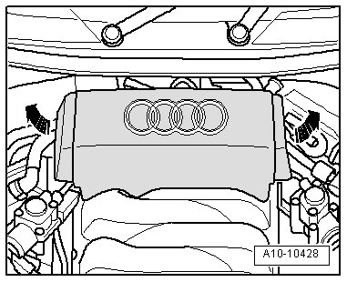
- Remove rear engine cover - arrows -.
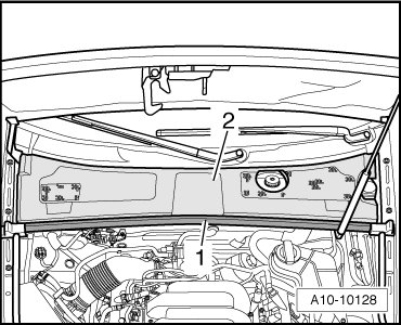
- Remove rubber seal - 1 - and remove plenum chamber cover - 2 -.
- Remove bolts - arrows -.
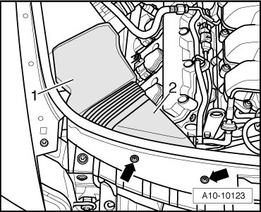
- Remove air guides - 1 - and - 2 -.
- Lay aside fuel line and line to EVAP canister at air filter housing and air guide pipe.
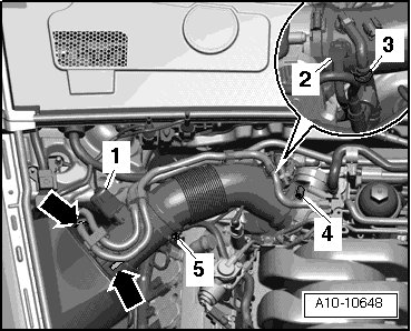
- Disconnect connector - 1 - for mass air flow sensor (G70).
- Remove air guide pipe from air filter housing, to do so release hose clamp - 5 - and open clips - arrows -.
• Ignore - 2, 3 and 4 -.
- Open clips - arrows - and remove upper air filter housing.
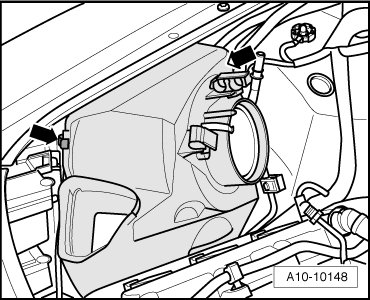
- Disconnect vacuum line - 1 -.
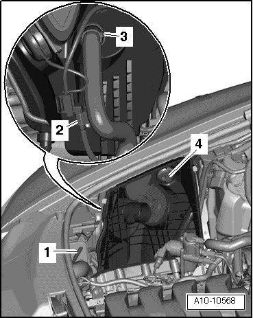
- Remove pin of expanding clip - 4 -.
- Remove lower air filter housing and disconnect electrical harness connector - 2 - at rear from EGR cooler switch-over valve (N345).
- Remove air guide hose - 3 - for Secondary Air Injection (AIR) pump, press release buttons to do so.
- Secure adapter (10 - 222 A /4) using binder (T40091/3) as well as supports (T40093/1) and (T40093/2) at suspension strut domes.
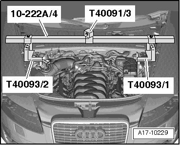
• Supports (T40093/1) are marked for left and right sides of vehicle.
- Assemble other components of (10 - 222 A) as depicted in illustration. Set supports (T40093/3) onto seams of longitudinal members.
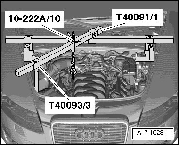
- Engage hook (10 - 222 A /10) in engine lifting eye.
- Pre-tension engine slightly using spindles of (10 - 222 A).
- Remove right front wheel.
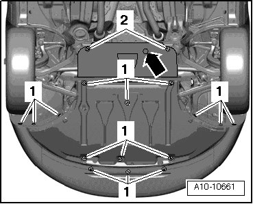
- Remove noise insulation, to do so loosen mounting parts - 1, 2 and arrow -.
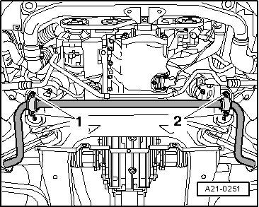
- Remove bolts - 1 - and - 2 - for left and right stabilizer mounts.
- Expose electrical wires at engine mount bracket.
- Remove nut - 3 -.
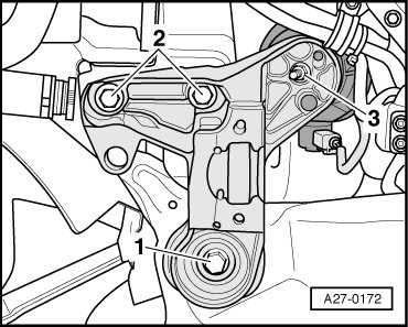
- Remove bolts - 1 - and - 2 - and remove right engine mount bracket.
- Disconnect connector - 1 - at right engine mount.
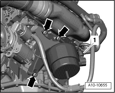
- Remove bolts - arrows -.
- Remove right engine support with engine mount.
- Remove bolts - arrows -.
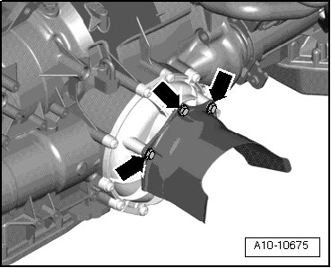
- Remove heat shields.
• B+ wire can only be removed after disconnecting electrical harness connector of terminal 50.
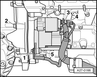
- Remove ground (GND) cable - 1 -.
- Remove electrical wires - 3 - and - 4 -.
- Remove bolts - 2 - and - 5 - and remove starter.
Installing
Install in reverse order of removal, observing the following:
• When installing, install cable ties at same location.
- Install right engine mount bracket.
- Install stabilizer.
- Connect battery. Required actions => [ Vehicles with : ] Battery, Disconnecting and Connecting.
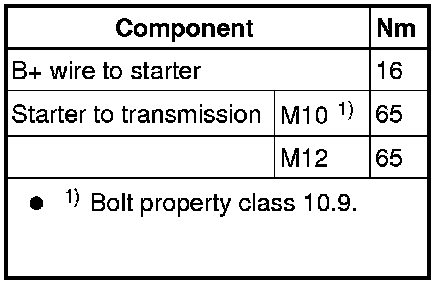
Tightening Specifications