Adjustment Procedure Using ACC Setting Device (VAS 6430)
Adjustment Procedure Using ACC Setting Device (VAS 6430)
Special tools, testers and auxiliary items required
• Vehicle Diagnostic, Testing and Information System (VAS 5051 B) with corresponding diagnostic cable.
• Diagnostic Cable (VAS 5051/5A)
• Wheel alignment computer
• ACC Setting Device (VAS 6430)
• Before driving the vehicle onto the alignment stand, check whether there is a sufficiently large space between the vehicle and the (VAS 6430). The distance between the (VAS 6430) and the vehicle must be 120 cm +/- 5 cm.
• If there is not sufficient space, drive vehicle backward on alignment stand in order to be able to use the corresponding space.
• Before performing the calibration procedure, check the position of the calibration mirror. The calibration mirror may need to be adapted before performing the calibration.
• The (VAS 6430) must be adapted before adjustment procedure. If this is done during the adjustment procedure, the pre-calibration on the (VAS 6430) must be repeated.
• Before beginning the adjustment, check the Diagnostic Trouble Code (DTC) memory and correct any malfunctions present.
The adjustment procedure is described here with the (VAS 6430).
• If there was a previous alignment, the steps under "Calibration procedure without a previous alignment" should not performed.
Calibration Procedure without a Previous Alignment
- Connect battery charger.
- Activate vehicle lift mode. Refer to => [ Vehicle Lift Mode ] Vehicle Lift Mode.
- Select the ACC calibration button on the alignment computer.
- Install quick clamps on the rear wheels.
- Install measuring sensors on the rear wheels.
- Perform a rim run-out compensation on the rear wheels.
• The (VAS 6430) must not be moved on the calibration beam.
Calibration Procedure with or without a Previous Alignment
- Remove license plate holder.
- Remove all contamination on sensor lens and inside of license plate holder.
- If necessary, remove the mirror installed at the center and install it all the way at the right near the vertical slits.
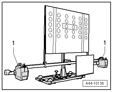
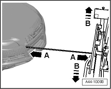
- Position (VAS 6430) at a distance - A - of 120 cm +/- 5 cm from sensor lens to mirror surface.
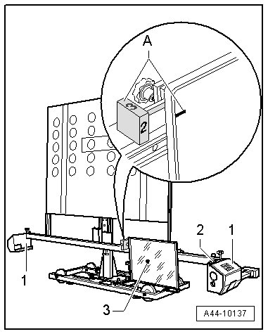
- Install the front wheel measuring sensors - 1 - on the (VAS 6430).
- In area - A -, bring item - 2 - on rotary knob into alignment with marking on the mirror (number 2 on rotary knob must face toward vehicle).
- Now align by sliding it sideways - arrows B - (VAS 6430) so that the laser beam is horizontally centered on the senor lens.
- Level the bubble levels - A and B - on the (VAS 6430) using the adjusting screws - 1, 2 and 3 -.
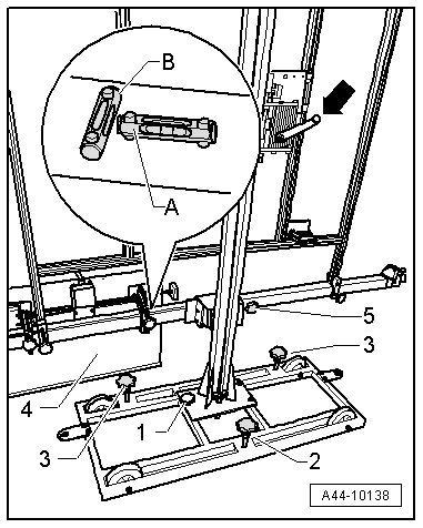
- Adjust the mirror - 4 - using the crank - arrow - on the (VAS 6430) so the laser beam is vertically centered on the sensor lens.
- Adjust the same front axle individual toe settings using the fine adjustment screw - 5 -.
- The difference between individual toe values must be less than 6' or they must be the same.
- Bring bubbles - 2 - on measurement sensor - 1 - into balance.
- Now using the laser beam - 3 - on the (VAS 6430) , check if the laser beam contacts sensor lens.
• If the laser beam still meets the sensor lens at this step after adjusting the same individual toe values, the (VAS 6430) is aligned correctly (positioned).
• If the laser beam does not meet the sensor lens, (VAS 6430) alignment must be performed again.
- Connect (VAS 5051/B).
- Connect (VAS 5051/5A) to Data Link Connector (DLC).
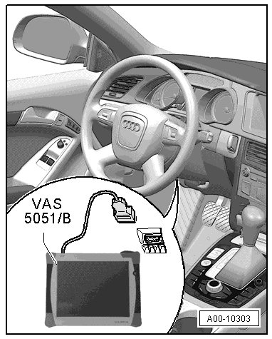
- Turn (VAS 5051/B) on.
Vehicle diagnosis, testing and information system is ready to operate when it displays operating modes in button fields.
- Turn on ignition.
- Touch Guided Fault Finding.
- Select in succession:
• Brand
• Type
• Model year
• Version
• Engine Code
- Confirm data entered.
Wait until the (VAS 5051/B) has checked all available control modules in vehicle.
- Press the go to button and select "function/component selection".
Then
- "Body (Repair Group 01; 27; 50 - 97)".
- "Electrical System (Repair group 01; 27; 50 - 97)".
- "01- On Board Diagnostic (OBD) capable systems".
- "13 - Distance control".
- "J428 - Distance Regulation Control Module, functions".
- "J428 - Distance regulation calibration".
Now follow instructions on screen to perform adjustment.
- Use the upper screw - 1 - and lower screw - 2 - for precision adjustment in "Guided Fault Finding".
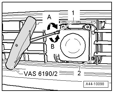
The ACC adjustment is only accepted if "actuator test ended" is displayed in (VAS 5051/B).
- Switch ignition off.
- Disconnect (VAS 5051/5A) connector from diagnostic connection.
- Disconnect battery charger.
- Install license plate holder.