P0117
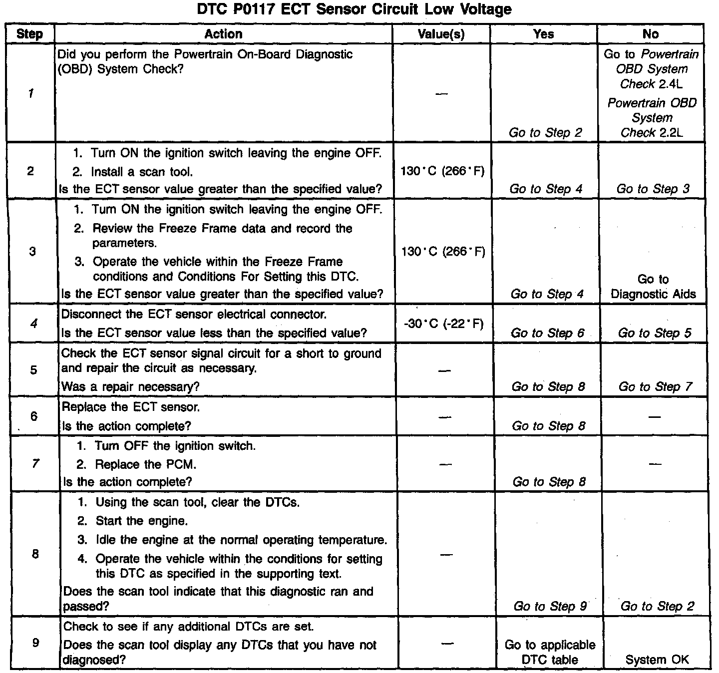
Diagnostic Chart:
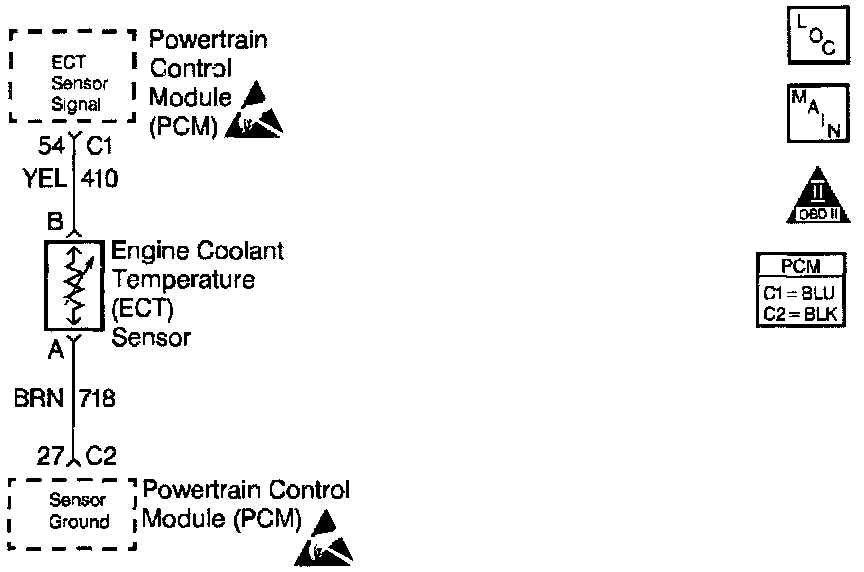
Wiring Diagram:
CIRCUIT DESCRIPTION
The Engine Coolant Temperature (ECT) sensor uses a thermistor in order to control the signal voltage to the Powertrain Control Module (PCM). The PCM supplies a voltage on the signal circuit to the sensor. When the engine is cold, the sensor resistance is high, therefore, the ECT signal voltage will be high.
As the engine warms, the sensor resistance becomes less and the voltage drops. At the normal engine operating temperature, the voltage will be between 1.5 and 2.0 volts at the ECT signal terminal.
The ECT sensor controls the following items:
^ The fuel delivery
^ The Torque Converter Clutch (TCC)
^ The Ignition Control (IC)
^ The Evaporative Emission (EVAP) canister purge valve
^ The Idle Air Control (IAC) valve
^ The Electric cooling fan
CONDITIONS FOR SETTING THE DTC
^ The engine run time is greater than 128 seconds.
^ The ECT sensor indicates that the engine coolant temperature is greater than 138°C (280°F) for 6.25 seconds.
ACTION TAKEN WHEN THE DTC SETS
^ The Malfunction Indicator Lamp (MIL) will illuminate.
^ The PCM will record the operating conditions at the time that the diagnostic fails. This information will store in the Freeze Frame and Failure Records buffers.
^ A history DTC stores.
^ The coolant fan turns ON.
^ The PCM will default to 20°C (66°F) for the first 60 seconds of the engine run time and then to 92°C (198°F). The scan tool may show the defaulted value.
CONDITIONS FOR CLEARING THE MIL/DTC
^ The MIL will turn OFF after three consecutive ignition cycles in which the diagnostic runs without a fault.
^ A history DTC will clear after 40 consecutive warm up cycles without a fault.
^ The MIL/DTC(s) can be cleared by using the scan tool.
DIAGNOSTIC AIDS
^ After the engine has started, the ECT should rise steadily to about 90°C (194°F). Then, the ECT should stabilize when the thermostat opens.
^ Use the Temperature vs. Resistance table in order to evaluate the possibility of a skewed sensor.
TEST DESCRIPTION
The number(s) below refer(s) to the step number(s) in the Diagnostic Table.
1. The Powertrain OBD System Check prompts you to complete some of the basic checks and to store the freeze frame and failure records data on the scan tool if applicable. This creates an electronic copy of the data captured when this DTC set. The scan tool stores this data for later reference.
4. This step simulates a DTC P0118. The PCM and the ECT wiring are OK if the PCM senses the change in the ECT sensor signal.
7. Reprogram the replacement PCM and perform the crankshaft position system variation learning procedure. Refer to the latest Techline information for PCM programming and the CKP System Variation Learn Procedure for the Crankshaft Position System Variation Learning Procedure.