B0367
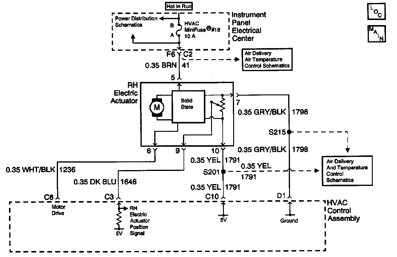
Schematic:
CIRCUIT DESCRIPTION
The HVAC Control Assembly receives a RH electric actuator position signal from the RH electric actuator. The RH electric actuator position sensor is a potentiometer that is tied to a 5 volt reference source through CKT 1791 and to ground through CKT 1798, both from the HVAC Control Assembly. The variable output from the potentiometer feeds back a position signal through CKT 1646 to a pull-up resistor located in the HVAC Control Assembly. This signal is used to determine the necessary drive signal to the RH electric actuator motor to provide the proper air mix door position. This value is stored in the Keep Alive Memory (KAM) portion of the HVAC Control Assembly.
CONDITIONS FOR SETTING THE DTC
^ With the ignition in the ON position, CKT 1646 is checked continuously.
^ CKT 1646 stays at 4.5 volts or higher.
ACTION TAKEN WHEN THE DTC SETS
^ The HVAC Control Assembly stores a DTC B0367 in memory.
^ No driver warning message will be displayed for this DTC.
CONDITIONS FOR CLEARING THE DTC
^ Using the IPC clearing feature.
^ Using a scan tool.
^ A history DTC will clear after 50 consecutive ignition cycles if the conditions for the fault is no longer present.
DIAGNOSTIC AIDS
^ If the DTC is a history or an intermittent. Try to perform the tests shown while "wiggling" wiring and connectors, this can often cause the malfunction to appear.
^ Visually inspect sensor connector and harness for damage, corrosion or water intrusion.
^ Check for adequate terminal tension, mis-routed harness, rubbed through wire insulation, and broken wire inside insulation.
^ Install a scan tool to the diagnostic link connector. Turn the ignition switch to the ON position. Select the OUTPUT CONTROL screen in HVAC special functions. Use the MISCELLANEOUS TEST screen to manually drive the RH electric actuator with the scan tool from fully open to fully closed. Monitor the RH MIX MTR POSITION FEEDBACK with the scan tool when this is done. A normal position feedback signal should range between 0-255 counts as the electric actuator is being moved.
TEST DESCRIPTION
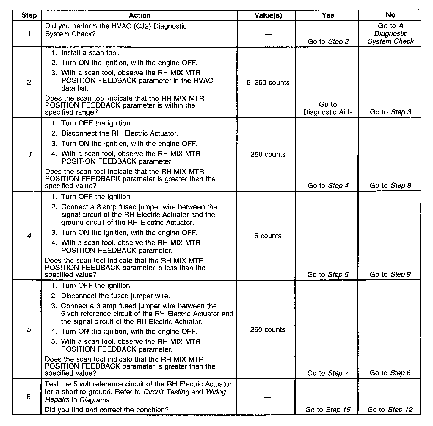
Steps 1-6:
Steps 7-15:
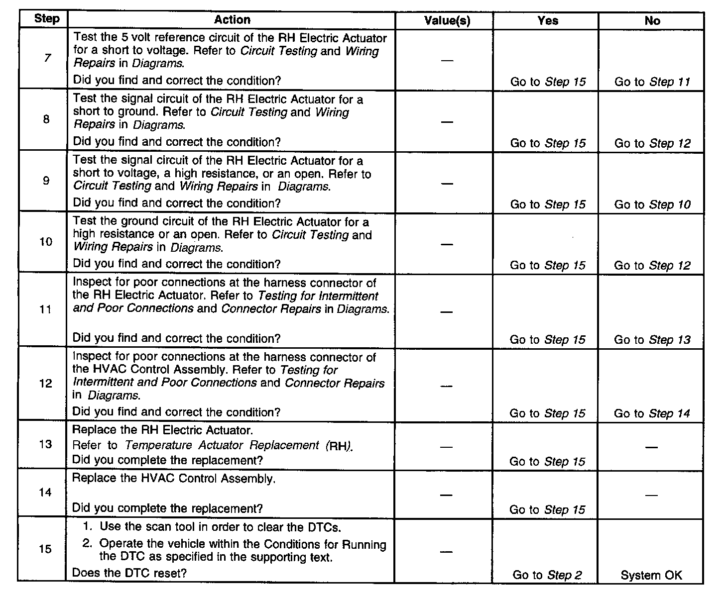
The number(s) below refer to the step number(s) on the diagnostic table.
3. Tests for the proper operation of the circuit in the high voltage range.
4. Tests for the proper operation of the circuit in the low voltage range. If the fuse in the jumper opens when you perform this test, the signal circuit is shorted to voltage.
5. Tests for a short to ground in the 5 volt reference circuit.
7. Tests for a short to voltage in the 5 volt reference circuit.