Malfunction Indicator Lamp (MIL) Inoperative
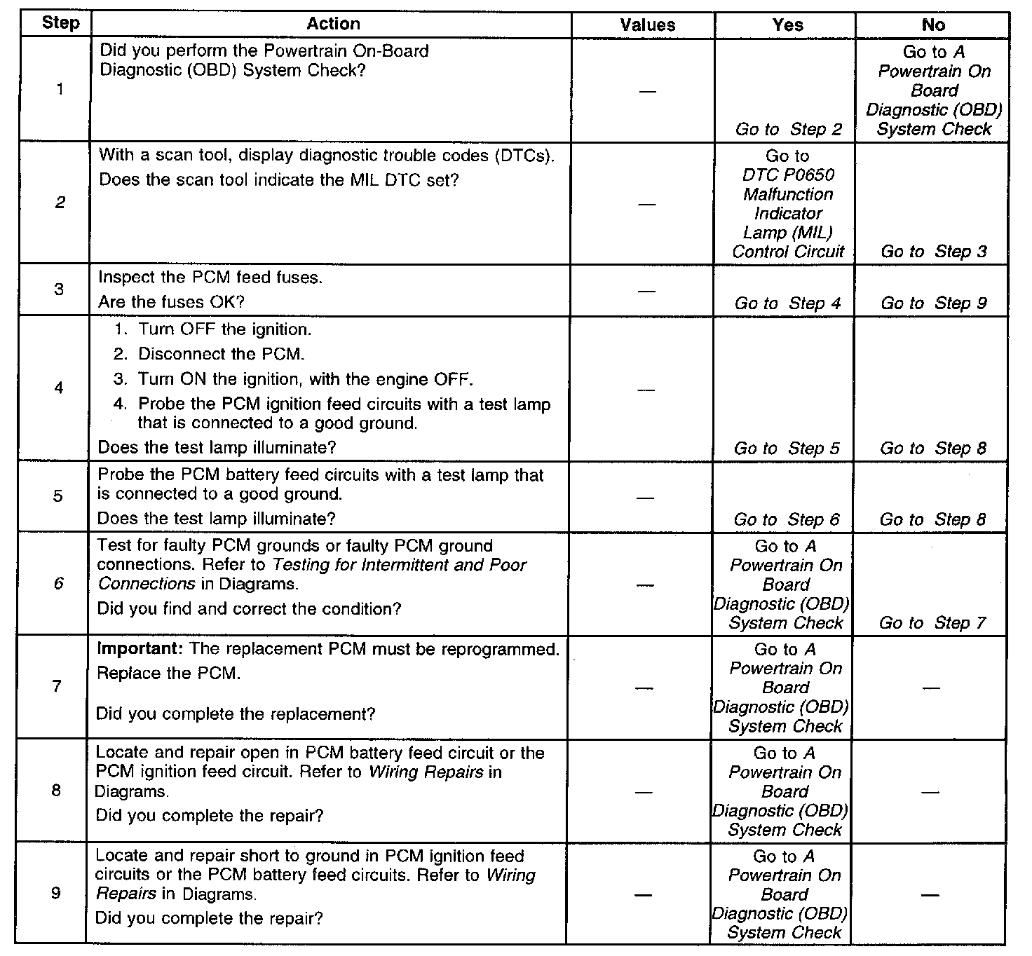
Diagnostic Chart:
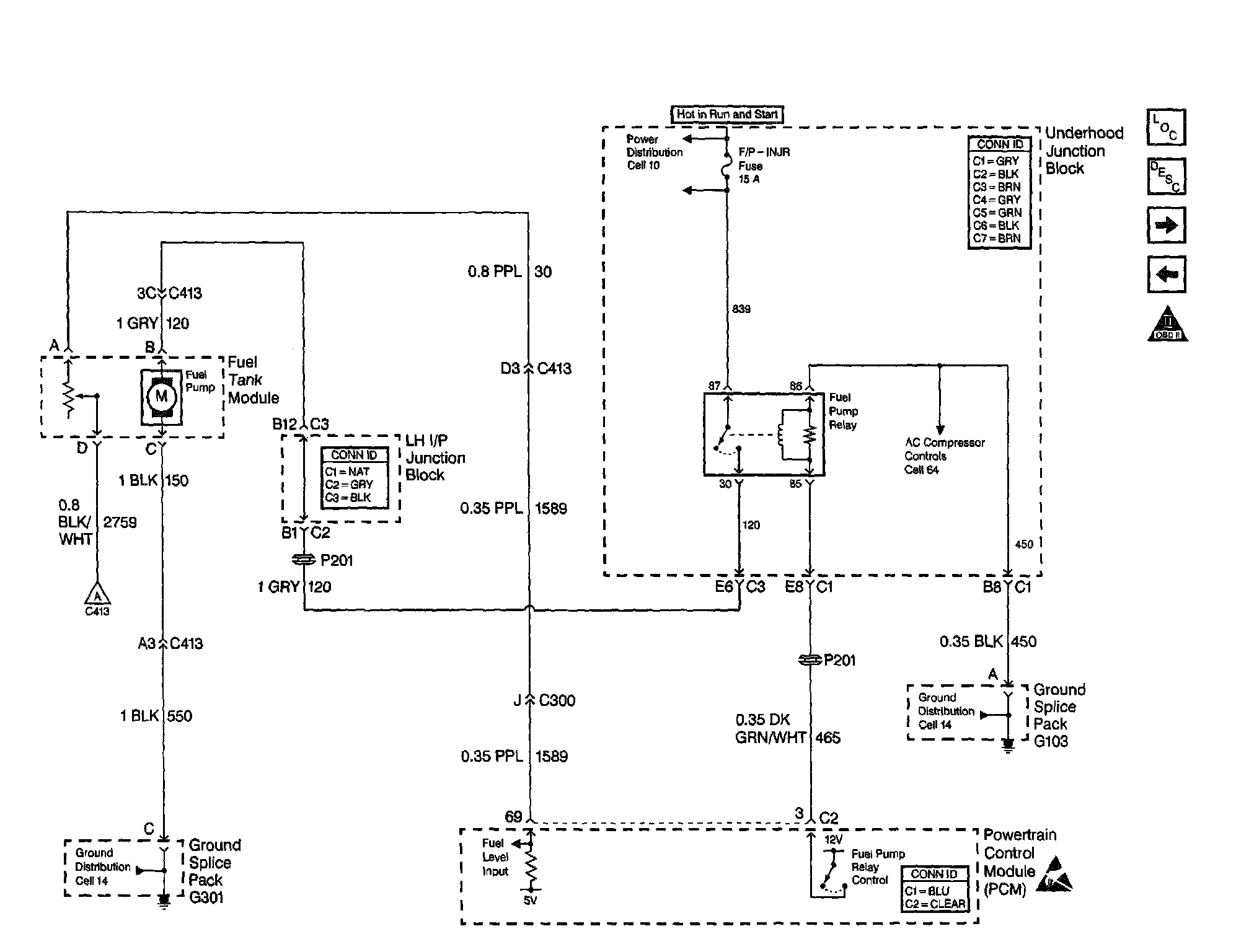
Engine Controls Schematics: Power, Ground, MIL And DLC:
CIRCUIT DESCRIPTION
There should be a steady malfunction indicator lamp (MIL) with the ignition ON and the engine OFF. Ignition feed voltage is supplied directly to the MIL. The powertrain control module (PCM) turns the MIL ON by grounding the MIL control circuit. No MIL with the key ON, engine not running and the MIL DTC set suggests an open in the MIL control circuit.
MIL OPERATION
The malfunction indicator lamp (MIL) is located on the instrument panel and is displayed as CHECK ENGINE lamp.
MIL FUNCTION
^ The MIL informs the driver that a malfunction has occurred and the vehicle should be taken in for service as soon as possible
^ The MIL illuminates during a bulb test and a system test
^ A DTC will be stored if a MIL is requested by the diagnostic
MIL ILLUMINATION
^ The MIL will illuminate with ignition ON and the engine OFF
^ The MIL will turn OFF when the engine is started
^ The MIL will remain ON if the self-diagnostic system has detected a malfunction
^ The MIL may turn OFF if the malfunction is not present
^ If the MIL is illuminated and then the engine stalls, the MIL will remain illuminated so long as the ignition is ON.
^ If the MIL is not illuminated and the engine stalls, the MIL will not illuminate until the ignition is cycled OFF, then ON.
POWERTRAIN ON BOARD DIAGNOSTIC (OBD) SYSTEM CHECK
Perform the Powertrain On Board Diagnostic (OBD) System Check, when the following conditions are present:
^ When the MIL does not turn ON when the ignition switch is turned to the RUN position. See above for MIL Operation
^ When the MIL remains ON while the engine is running
^ When the MIL is flashing while the engine is running
^ When a driveability symptom is determined
DIAGNOSTIC AIDS
An intermittent may be caused by a faulty connection, rubbed through wire insulation or a wire broken inside the insulation. Inspect the following items:
Inspect the PCM harness and connectors for improper mating, broken locks, improperly formed or damaged terminals, faulty terminal to wire connection, and damaged harness.
^ If the engine runs OK, inspect for a malfunctioning MIL, an open in the MIL control circuit, or an open in the instrument cluster ignition feed.
^ If the engine cranks but will not run, inspect for an open PCM ignition or battery feed or a faulty PCM to engine ground.
TEST DESCRIPTION
The numbers below refer to the step numbers on the diagnostic table.
2. If the MIL DTC is set, the MIL Control Circuit table will better diagnose the condition.
6. Using a test lamp connected to battery positive voltage, probe each of the PCM ground terminals to ensure that a good ground is present.