Engine Controls (w/Throttle Actuator Control)
DTC P0121, P0122, P0123, P0221, P0222, or P0223 (w/Throttle Actuator Control)
DTC Descriptors
DTC P0121
- Throttle Position (TP) Sensor 1 Performance
DTC P0122
- Throttle Position (TP) Sensor 1 Circuit Low Voltage
DTC P0123
- Throttle Position (TP) Sensor 1 Circuit High Voltage
DTC P0221
- Throttle Position (TP) Sensor 2 Performance
DTC P0222
- Throttle Position (TP) Sensor 2 Circuit Low Voltage
DTC P0223
- Throttle Position (TP) Sensor 2 Circuit High Voltage
Diagnostic Fault Information
Perform the Diagnostic System Check - Vehicle Diagnostic System Check - Vehicle prior to using this diagnostic procedure.

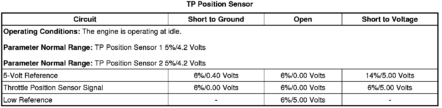
Typical Scan Tool Data
Circuit/System Description
The throttle body assembly contains 2 throttle position (TP) sensors. The TP sensors are mounted to the throttle body assembly and are not serviceable. The TP sensors provide a signal voltage that changes relative to throttle blade angle. The engine control module (ECM) supplies the TP sensors with a common 5-volt reference circuit, a common low reference circuit, and 2 independent signal circuits.
The TP sensors have opposite functionality. TP sensor 1 signal voltage increases from below 1 volt at idle to above 4 volts at wide open throttle (WOT). TP sensor 2 signal voltage decreases from above 4 volts at idle to below 1 volt at WOT.
Conditions for Running the DTC
P0121 or P0221
* DTCs P0101, P0102, P0103, P0106, P0107, or P0108 are not set.
* The ignition is ON or the engine is operating.
* The actual TP value is less than 90°.
* The DTCs run continuously when the above conditions are met.
P0122, P0123, P0221, or P0223
* The ignition is ON or the engine is operating.
* The DTCs run continuously when the above condition is met.
Conditions for Setting the DTC
P0121 or P0221
The ECM detects the difference between TP sensor 1 and TP sensor 2 is greater than 6° for less than 1 second.
P0122
The ECM detects that the TP sensor 1 voltage is less than 0.044 volt for less than 1.5 seconds.
P0123
The ECM detects that the TP sensor 1 voltage is greater than 4.658 volts for less than 1.5 seconds.
P0222
The ECM detects that the TP sensor 2 voltage is less than 0.124 volt for less than 1.5 seconds.
P0223
The ECM detects that the TP sensor 2 voltage is greater than 4.91 volts for less than 1.5 seconds.
Action Taken When the DTC Sets
DTCs P0122, P0123, P0222, and P0223 are Type B DTCs.
DTC P2135 is a type A DTC.
Conditions for Clearing the DTC
DTCs P0121 and P0221 are type B DTCs.
DTCs P0122, P0123, P0222, and P0223 are Type A DTCs.
Reference Information
Schematic Reference
Engine Controls Schematics Electrical Diagrams
Connector End View Reference
* Engine Control Module (ECM) Connector End Views Engine Control Module (ECM) Connector End Views
* Engine Controls Connector End Views Engine Controls Connector End Views
Electrical Information Reference
* Circuit Testing Circuit Testing
* Connector Repairs Connector Repairs
* Testing for Intermittent Conditions and Poor Connections Testing for Intermittent Conditions and Poor Connections
* Wiring Repairs Wiring Repairs
DTC Type Reference
Diagnostic Trouble Code (DTC) Type Definitions Diagnostic Trouble Code (DTC) Type Definitions
Scan Tool Reference
* Scan Tool Data List (w/o Throttle Actuator Control) Scan Tool Data List (w/o Throttle Actuator Control)Scan Tool Data List (w/Throttle Actuator Control) Scan Tool Data List (w/Throttle Actuator Control)
* Scan Tool Data Definitions Scan Tool Data Definitions
* Scan Tool Output Controls Scan Tool Output Controls
Circuit/System Verification
1. Ignition ON, observe the TP Sensor parameters with a scan tool. Verify both of the TP sensor voltages are between 0.4-4.5 volts.
2. Rapidly depress the accelerator pedal from the rest position to the WOT position and release pedal. Repeat the procedure several times. DTCs P0121, P0122, P0123, P0221, P0222, or P0223 should not set.
3. Slowly depress the accelerator pedal to WOT and then slowly return the pedal to closed throttle. Repeat the procedure several times. DTCs P0121, P0122, P0123, P0221, P0222, or P0223 should not set.
4. If the vehicle passes the Circuit/System Verification Test, then operate the vehicle within the conditions for running the DTC. You may also operate the vehicle within the conditions that are captured in the Freeze Frame/Failure Records Data List.
Circuit/System Testing
1. Ignition OFF, disconnect the harness connector of the throttle body assembly.
2. Ignition OFF, test for less than 5 ohms of resistance between the low reference circuit of the TP sensor and ground.
• If greater than 5 ohms, test the low reference circuit of the TP sensor for a short to voltage, or an open/high resistance. If the circuit/connections test normal, replace the ECM.
Important: The 5-volt reference circuits are internally and externally connected at the ECM. Other component DTCs may be set. If other DTCs are set, review the electrical schematic and diagnose the applicable circuits and components.
3. Ignition ON, test for 4.8-5.2 volts between the 5-volt reference circuit of the TP sensor and ground.
• If less than 4.8 volts, test the 5-volt reference circuit of the TP sensor for a short to ground or open/high resistance. If the circuit/connections test normal, replace the ECM.
• If greater than 5.2 volts, test the 5-volt reference circuit of the TP sensor for a short to voltage. If the circuit/connections test normal, replace the ECM.
4. Using a scan tool, verify the TP sensor voltage parameter is less than 0.3 volt.
• If greater than 0.3 volt, test the signal circuit of the applicable TP sensor for a short to voltage. If the circuit/connections test normal, replace the ECM.
5. Install a 3-amp fused jumper wire between the appropriate signal circuit and the 5-volt reference circuit of the TP sensor. Verify the TP sensor voltage parameter is greater than 4.8 volts.
• If less than 4.8 volts, test the appropriate signal circuit of the TP sensor for a short to ground or an open/high resistance. If the circuit/connections test normal, replace the ECM.
• If both TP sensor voltage parameters display greater than 4.8 volts test the signal circuits of the TP sensors for a shorted together condition. If the circuit/connections test normal, replace the ECM.
6. If all circuits/connections test normal, test or replace the throttle body assembly.
Component Testing
TP Sensor
1. Ignition OFF, disconnect the harness connector of the throttle body assembly.
2. Measure for 1,160-1,175 ohms between the 5-volt reference and the low reference terminals of the applicable TP sensor.
• If the resistance is not within the specified range, replace the throttle body assembly.
3. Measure the resistance between the signal terminal and the low reference terminal of the throttle body assembly. Sweep the TP sensor through the entire range. The resistance should vary between 1530 and 630 ohms without any spikes or dropouts.
• If the resistance is not within the specified range or is erratic, replace the throttle body assembly.
4. Apply 5 volts and ground to the applicable terminals of the TP sensor, and measure the voltage between the signal and the low reference terminals. Sweep the TP sensor through the entire range. The voltage should vary between 4.3-0.6 volts without any spikes or dropouts.
• If the voltage is not within the specified range or is erratic, replace the throttle body assembly.
Repair Instructions
Perform the Diagnostic Repair Verification Diagnostic Repair Verification after completing the diagnostic procedure.
* Throttle Body Assembly Replacement Removal and Replacement
* Control Module References Programming and Relearning for engine control module replacement, setup, and programming