Air Conditioning Compressor Malfunction
Air Conditioning Compressor Malfunction
Diagnostic Instructions
* Perform the Diagnostic System Check - Vehicle Diagnostic System Check - Vehicle prior to using this diagnostic procedure.
* Review Strategy Based Diagnosis Strategy Based Diagnosis for an overview of the diagnostic approach.
* Diagnostic Procedure Instructions Diagnostic Procedure Instructions provides an overview of each diagnostic category.
Diagnostic Fault Information
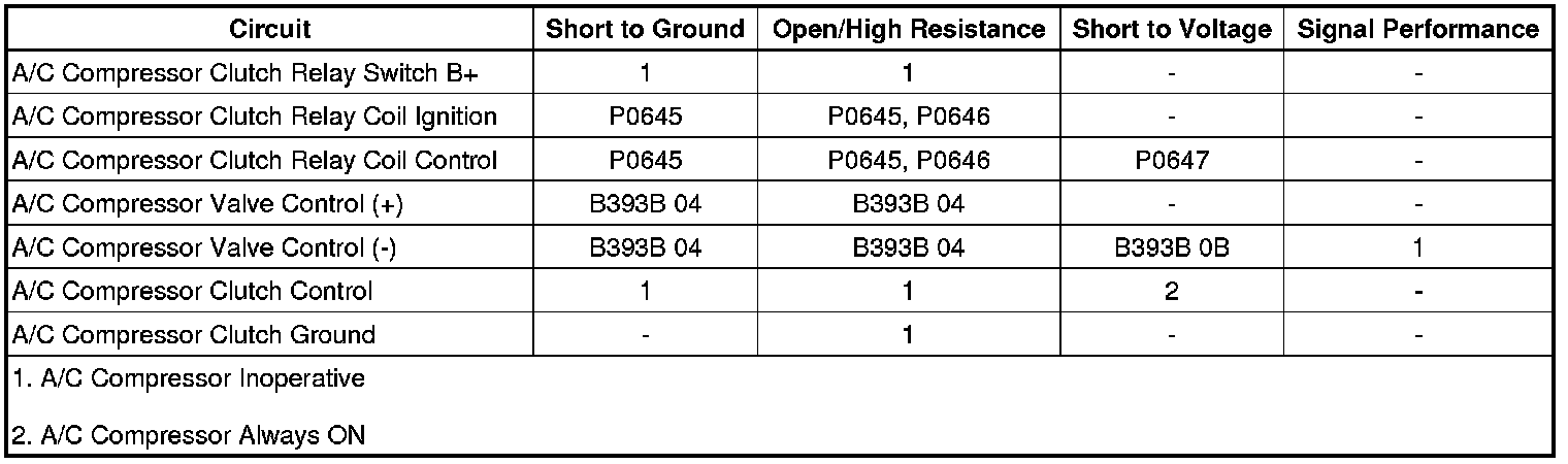
Circuit/System Description
The A/C compressor is belt driven and operates when the magnetic clutch is engaged. When the A/C switch is pressed, the HVAC control module sends an A/C request message to the ECM via CAN-Bus. Therefore the ECM grounds the A/C compressor clutch relay control circuit, which will switch the A/C compressor clutch relay. With the relay contacts closed, battery voltage is supplied to the A/C compressor clutch. The A/C compressor clutch will be activated.
The performance of the A/C compressor is regulated per a lifting magnet in the A/C compressor. The HVAC control module supplies battery voltage to the A/C compressor. When the A/C switch is pressed, the HVAC control module provides a pulse width modulation (PWM) signal to the A/C compressor in order to command the performance of the A/C compressor. The performance of the A/C compressor is regulated according to adjusted interior temperature on the basis of characteristic lines. Therefore the HVAC control module grounds the A/C compressor with the PWM signal.
Diagnostic Aids
The following conditions must be met in order to turn on the A/C compressor:
* Battery voltage is between 9-18 V
* Engine coolant temperature is less than 124°C (255°F)
* Engine speed is greater than 600 RPM
* Engine speed is less than 5 500 RPM
* A/C high side pressure is between 269-2 929 kPa (39-425 PSI)
* Throttle position is less than 100%
* Evaporator temperature is greater than 3°C (38°F)
* ECM does not detect immoderate torque load
* ECM does not detect insufficient idle quality
* The ambient temperature is above 1°C (34°F)
Reference Information
Schematic Reference
HVAC Schematics HVAC - Automatic
Connector End View Reference
Component Connector End Views Sunshade - Left (DH6)
Description and Operation
Automatic HVAC Description and Operation HVAC - Automatic
Electrical Information Reference
* Circuit Testing Circuit Testing
* Connector Repairs Connector Repairs
* Testing for Intermittent Conditions and Poor Connections Testing for Intermittent Conditions and Poor Connections
* Wiring Repairs Wiring Repairs
Scan Tool Reference
Control Module References Control Module References for scan tool information
Circuit/System Testing
Note:
Before executing Circuit/System Testing, all conditions shown in Diagnostic Aids must be met.
1. Ignition ON, activate and deactivate the A/C switch. Verify the scan tool A/C Switch parameter changes between Active and Inactive.
• If the parameter does not change
Replace the A26 HVAC Controls.
• If the parameter changes
2. Activate and deactivate the A/C switch. Verify the engine control module (ECM) scan tool A/C Request Signal parameter changes between Active and Inactive.
• If the parameter does not change
Replace the K33 HVAC Control Module.
• If the parameter changes
3. Ignition OFF, remove the KR29 A/C Compressor Clutch Relay, ignition ON.
4. Verify that a test lamp illuminates between the B+ circuit terminal 30 and ground.
• If the test lamp does not illuminate and the circuit fuse is good
1. Ignition OFF.
2. Test for less than 2 ohms in the B+ circuit end to end.
• If greater than 2 ohms, repair the open/high resistance in the circuit.
• If less than 2 ohms, verify the fuse is not open and there is voltage at the fuse.
• If the test lamp does not illuminate and the circuit fuse is open
1. Ignition OFF.
2. Test for infinite resistance between B+ circuit and ground.
• If less than infinite resistance, repair the short to ground on the circuit.
• If infinite resistance
3. Disconnect the X2 harness connector at the G1 A/C Compressor.
4. Test for infinite resistance between control circuit terminal 87 and ground.
• If less than infinite resistance, repair the short to ground on the circuit.
• If infinite resistance
5. Connect the X2 harness connector at the G1 A/C Compressor.
6. Connect a 10 A fused jumper wire between B+ and the control circuit terminal 87. Verify the fuse is good.
• If the fuse is open, replace the G1 A/C Compressor.
• If the fuse is good, replace the KR29 A/C Compressor Clutch Relay.
• If the test lamp illuminates
5. Verify that a test lamp does not illuminate between the control circuit terminal 87 and ground.
• If the test lamp illuminates
Repair the short to voltage on the circuit.
• If the test lamp does not illuminate
6. Connect a 10 A fused jumper wire between the B+ circuit terminal 30 and the control circuit terminal 87. Verify the G1 A/C Compressor is activated.
• If the G1 A/C Compressor is not activated
1. Ignition OFF, disconnect the X2 harness connector at the G1 A/C Compressor.
2. Test for less than 5 ohms between the ground circuit terminal 1 X2 and ground.
• If 5 ohms or greater, repair the open/high resistance in the circuit.
• If less than 5 ohms
3. Test for less than 2 ohms between the control circuit terminal 87 and the control circuit terminal 2 X2.
• If 2 ohms or greater, repair the open/high resistance in the circuit.
• If less than 2 ohms, replace the G1 A/C Compressor.
• If the G1 A/C Compressor is activated
7. Connect a test lamp between the ignition circuit terminal 85 and the control circuit terminal 86.
8. Command the engine control module (ECM) A/C Relay output function ON and OFF with the scan tool. The test lamp should turn ON and OFF when changing between the commanded states.
• If the test lamp always illuminates or does not illuminate
Replace the K20 Engine Control Module.
• If the test lamp illuminates as commanded
9. Connect the KR29 A/C Compressor Clutch Relay. Command the engine control module (ECM) A/C Relay output function ON and OFF with the scan tool. The G1 A/C Compressor should click when changing between the commanded states.
• If the G1 A/C Compressor does not click
Replace the KR29 A/C Compressor Clutch Relay.
• If the G1 A/C Compressor clicks
10. Replace the K33 HVAC Control Module. Engine running. Verify the G1 A/C Compressor works properly.
• If the G1 A/C Compressor does not work
Replace the G1 A/C Compressor.
• If the G1 A/C Compressor works properly
11. All OK.
Repair Instructions
Perform the Diagnostic Repair Verification Verification Tests after completing the diagnostic procedure.
* Air Conditioning Compressor Replacement (LE9) Air Conditioning Compressor Replacement (LE9)Air Conditioning Compressor Replacement (V6) Air Conditioning Compressor Replacement (V6)
* Heater and Air Conditioning Control Replacement Heater and Air Conditioning Control Replacement
* Control Module References Control Module References for HVAC Control Module or Engine Control Module replacement, programming and setup