Pinpoint Test H: The Air Conditioning (A/C) is Inoperative - Defrost and Floor/Defrost Modes Only
Climate Control System
Pinpoint Test H: The Air Conditioning (A/C) is Inoperative - Defrost and Floor/Defrost Modes Only
Refer to Wiring Diagrams Set 54, Manual Climate Control System for schematic and connector information. Electrical Diagrams
Normal Operation
The function selector switch is grounded. When the switch is closed, ground is provided to Generic Electronic Module (GEM) defrost circuit input from the function selector switch.
This pinpoint test is intended to diagnose the following:
- Wiring, terminals or connectors
- Function selector switch
- GEM (Generic Electronic Module)
PINPOINT TEST H : THE AIR CONDITIONING (A/C) IS INOPERATIVE - DEFROST AND FLOOR/DEFROST MODES ONLY
NOTE: Before carrying out the following test, diagnose any PCM, GEM (Generic Electronic Module) or Instrument Cluster (IC) DTCs.
H1 CHECK THE CLIMATE CONTROL / DEFROSTER (DEFROST_SW) GEM (Generic Electronic Module) PID
- Start the engine.
- Enter the following diagnostic mode on the scan tool: GEM (Generic Electronic Module) DataLogger.
- With the engine running, place the blower motor switch in the lowest position.
- Place the function selector switch to the DEFROST position while monitoring the DEFROST_SW GEM (Generic Electronic Module) PID.
Does the DEFROST_SW GEM (Generic Electronic Module) PID read ACTIVE?
Yes
GO to H5.
No
GO to H2.
H2 CHECK THE VOLTAGE TO THE FUNCTION SELECTOR SWITCH FOR GROUND
- Disconnect: Function Selector Switch C294.
- Measure the resistance between function selector switch C294-1, circuit 91-FA20 (BK/YE), harness side and ground.
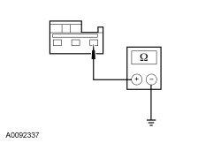
Is the resistance less than 5 ohms?
Yes
GO to H3.
No
REPAIR circuit 91-FA20 (BK/YE) for an open. TEST the system for normal operation.
H3 CHECK THE FUNCTION SELECTOR SWITCH
- Start the engine.
- Place the blower motor switch in the lowest position.
- Connect a fused jumper between function selector switch C294-1, circuit 91-FA20 (BK/YE), harness side and C294-3, circuit 91S-FA20 (BK/YE), harness side.
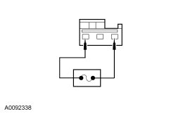
Does the A/C compressor operate?
Yes
INSTALL a new function selector switch. TEST the system for normal operation.
No
GO to H4.
H4 CHECK THE FUNCTION SELECTOR SWITCH INPUT CIRCUIT FOR AN OPEN
- Ignition OFF.
- Disconnect: GEM (Generic Electronic Module) C201C.
- Measure the resistance between function selector switch C294-3, circuit 91S-FA20 (BK/YE), harness side and GEM (Generic Electronic Module) C201C-22, circuit 91S-FA20 (BK/YE), harness side.
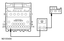
Is the resistance less than 5 ohms?
Yes
GO to H5.
No
REPAIR circuit 91S-FA20 (BK/YE) for an open. TEST the system for normal operation.
H5 CHECK THE GEM (Generic Electronic Module) CONNECTION
- Clear the DTCs.
- Disconnect all the GEM (Generic Electronic Module) connectors.
- Check for:
- corrosion
- pushed-out pins
- incorrectly seated connector
- Connect and correctly seat all the GEM (Generic Electronic Module) connectors.
- Operate the system.
Does the concern return?
Yes
INSTALL a new GEM (Generic Electronic Module). TEST the system for normal operation.
No
The system is operating correctly at this time. The concern may have been caused by a loose or corroded connector.