C1282
DTC C1282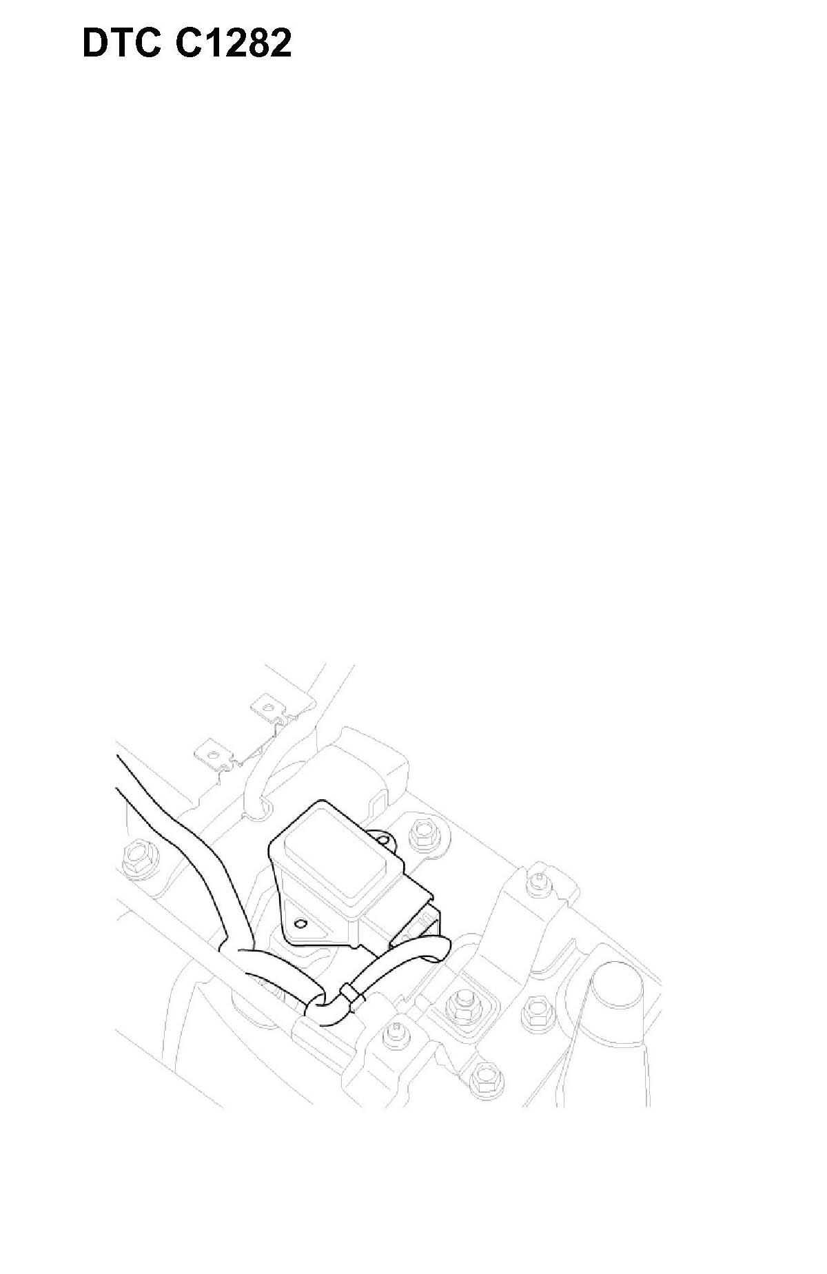
GENERAL DESCRIPTION
Both the yaw-rate sensor and later G sensor is installed in lower floor. The yaw-rate sensor detecting the rotation angular velocity calculates a difference with a target amount of turning, the lateral G sensor detecting slip of the vehicle compensates a target amount of turning. Direction and magnitude of lateral G loaded to vehicle can be known with electrostatic capacity changing according to lateral G. The output voltage of the lateral G sensor is 2.5 V when the vehicle is at a standstill.
DTC DESCRIPTION
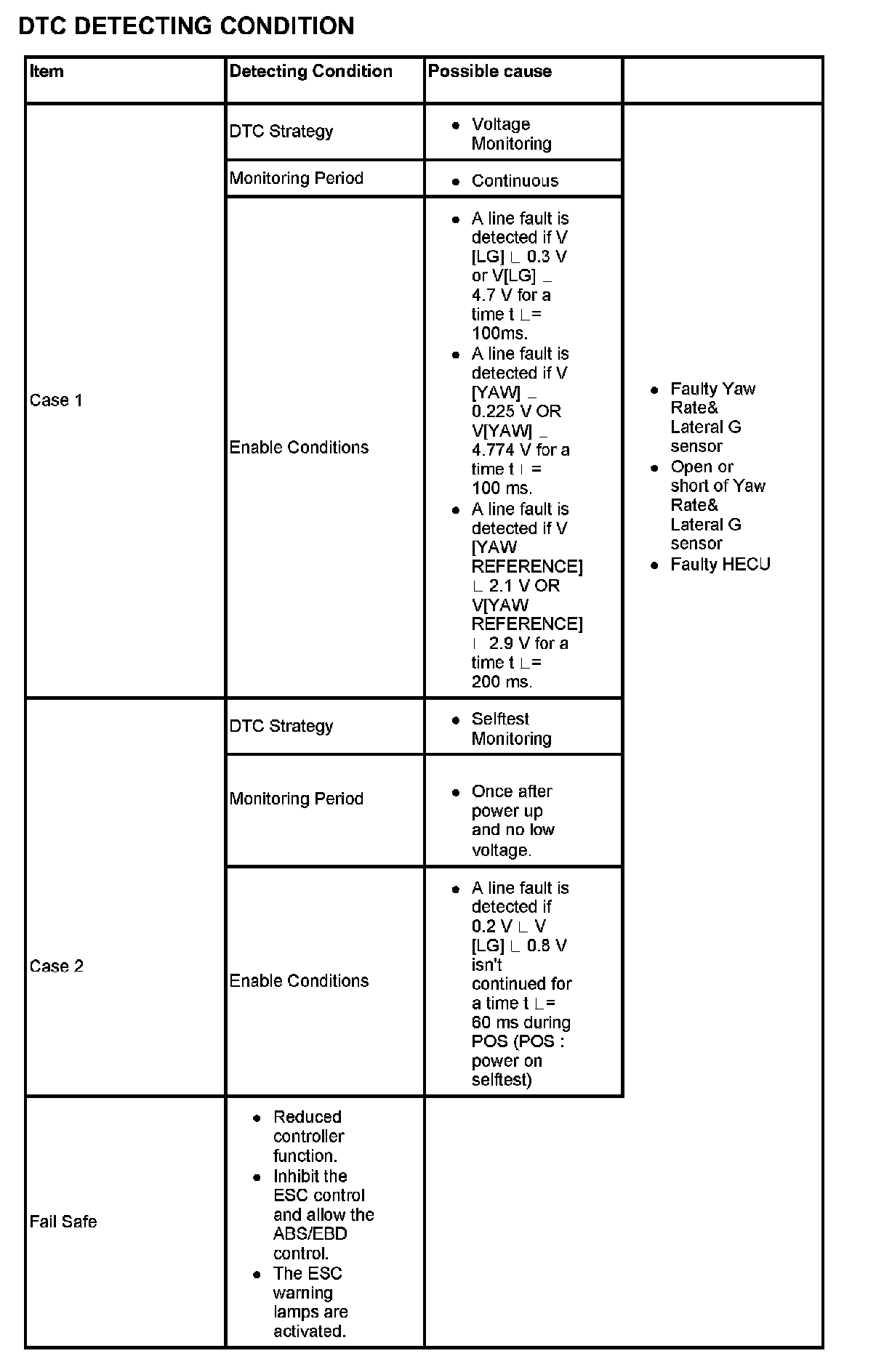
The HECU monitors a signal voltage of either yaw-rate sensor or later G sensor to detect open or short to battery or short to ground. A failure is detected if the lateral acceleration sensor or yaw rate sensor signal voltage stays in the fault range longer than the 100 ms or the lateral acceleration sensor or yaw rate sensor reference voltage stays in the fault range longer than the 200 ms, or the self test form is against specification during self test.
DTC DETECTING CONDITION:
MONITOR SCANTOOL DATA
1. Connect Scantool to Data Link Connector (DLC).
2. Ignition "ON".
3. Monitor the "Yaw rate sensor-lateral & Yaw rate sensor-yaw" parameter on the Scantool.
Specification: Lateral G sensor: ° 0 G, YAW rate Sensor: ° 0 deg/s
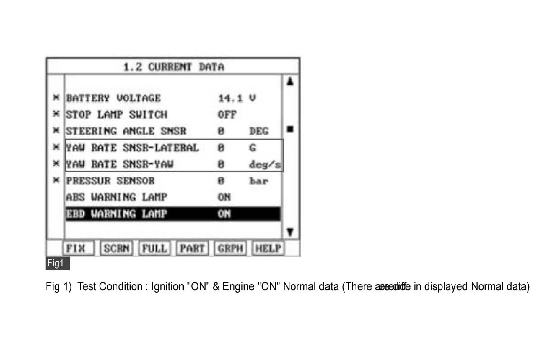
4. Is parameter displayed within specifications?
YES
Fault is intermittent caused by poor connection in Yaw Rate & Lateral G sensor harness and/or HECU's connector or was repaired and HECU memory was not cleared. Thoroughly check connectors for looseness, poor connection, bending, corrosion, contamination, deterioration, or damage. Repair or replace as necessary and then go to "Verification of Vehicle Repair" procedure.
NO
Go to "W/Harness Inspection" procedure.
TERMINAL & CONNECTOR INSPECTION
1. Many malfunctions in the electrical system are caused by poor harness(es) and terminals. Faults can also be caused by interference from other electrical systems, and mechanical or chemical damage.
2. Thoroughly check connectors for looseness, poor connection, bending, corrosion, contamination, deterioration, or damage.
3. Has a problem been found?
YES
Repair as necessary and then go to "Verification of Vehicle Repair" procedure.
NO
Go to "Power Circuit Inspection" procedure.
POWER SUPPLY CIRCUIT INSPECTION
1. Ignition "ON" & Engine "OFF".
2. Measure voltage between terminal "1" of the Yaw Rate & Lateral G sensor harness connector and chassis ground.
Specification: Approx. B+
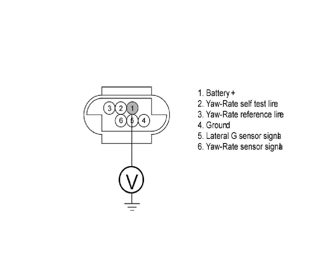
3. Is the measured voltage within specifications?
YES
Go to "Ground Circuit Inspection" procedure.
NO
Check for open or short to GND in the Yaw Rate & Lateral G sensor harness between terminal "1" of the Yaw Rate & Lateral G sensor harness connector and battery +. Repair as necessary and then go to "Verification of vehicle Repair" procedure.
GROUND CIRCUIT INSPECTION
1. Ignition "OFF".
2. Disconnect Yaw Rate & Lateral G sensor connector.
3. Measure resistance between terminal "4" of the Yaw Rate & Lateral G sensor harness connector and chassis ground.
Specification: Approx. below 1
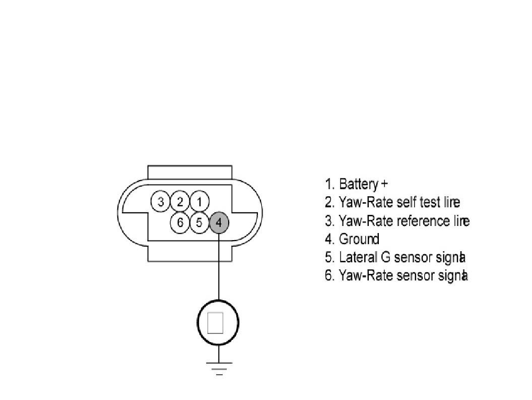
4. Is the measured resistance within specifications?
YES
Go to "Signal Circuit Inspection" procedure.
NO
Check for open or short in the Yaw Rate & Lateral G sensor harness between terminal "4" of the Yaw Rate & Lateral G sensor harness connector and chassis ground. Repair as necessary and then go to "Verification of vehicle Repair" procedure.
SIGNAL CIRCUIT INSPECTION
1. Ignition "ON" & Engine "OFF".
2. Measure voltage between terminal "3,5,6" of the Yaw Rate & Lateral G sensor harness connector and chassis ground.
Specification: Approx. 2.5 V (Voltage between terminal "5, 6" of the Yaw Rate & Lateral G sensor harness connector and chassis ground.)
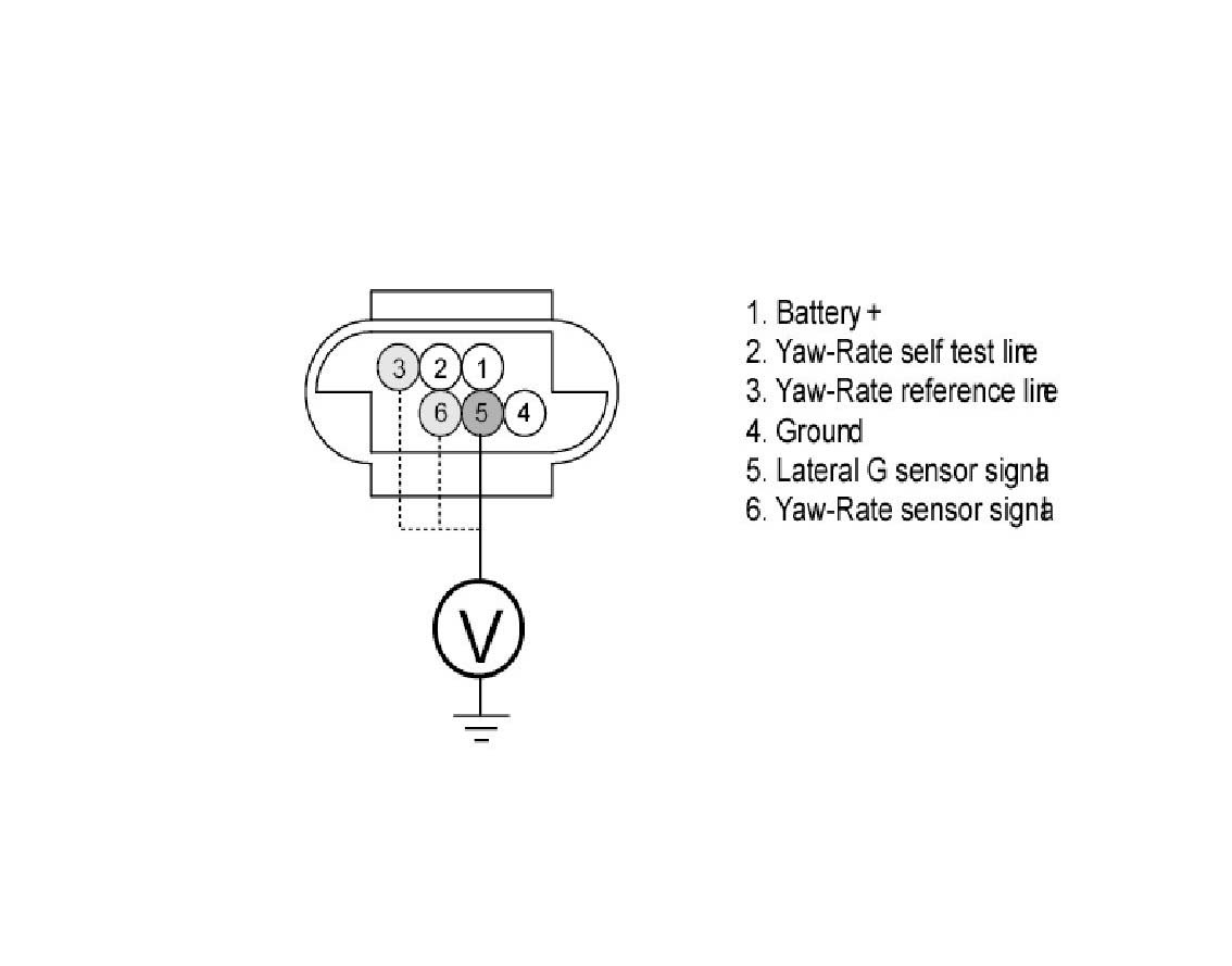
3. Is the measured resistance within specifications?
YES
Go to "Self Test Circuit Inspection" procedure.
NO
Check for open or short in the Yaw Rate & Lateral G sensor harness between terminal "3, 5, 6" of the Yaw Rate & Lateral G sensor harness connector and terminal "16, 18, 20" of the chassis ground. Repair as necessary and then go to "Verification of vehicle Repair" procedure. If OK, Substitute with a known-good Yaw Rate & Lateral G sensor and check for proper operation. If problem is corrected, replace sensor and then go to "Verification of Vehicle Repair" procedure.
SELF TEST CIRCUIT INSPECTION
1. Measure wave between terminal "2" of the Yaw Rate & Lateral G sensor harness connector and chassis ground.
Specification: Approx. 0.2V L Voltage L 0.8V (during Ignition "ON")
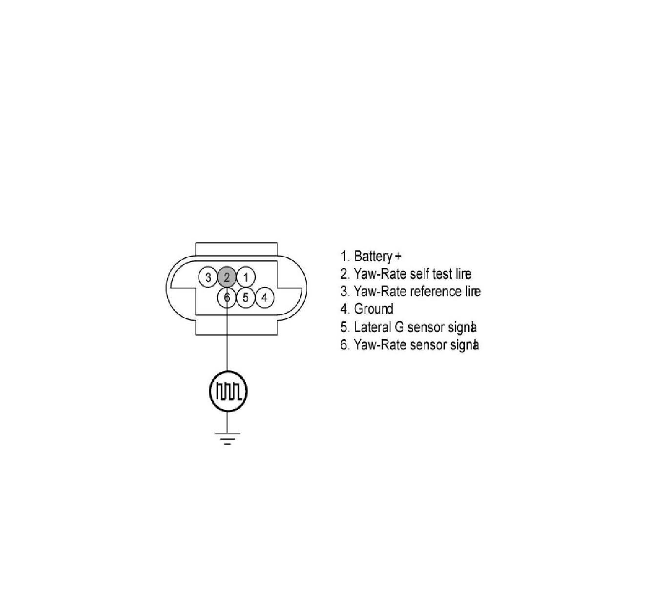
2. Is the measured wave within specifications?
YES
Go to "Component Inspection" procedure.
1. Ignition "OFF".
2. Engine "ON".
3. Does warning lamp remain On?
YES
Substitute with a known-good HECU and check for proper operation. If problem is corrected, replace HECU and then go to "Verification of Vehicle Repair" procedure.
NO
Fault is intermittent caused by poor connection in Yaw Rate & Lateral G sensor circuit and/or faulty Yaw Rate & Lateral G sensor or was repaired and HECU memory was not cleared. Go to the applicable troubleshooting procedure.
VERIFICATION OF VEHICLE REPAIR
After a repair, it is essential to verify that the fault has been corrected.
1. Connect Scantool and select "Diagnostic Trouble Codes (DTCs)" mode
2. Using a Scantool, clear DTC.
3. Operate the vehicle within DTC Detecting Condition in General Information.
4. Are any DTCs present?
YES
Go to the applicable troubleshooting procedure.
NO
System performing to specification at this time.