P2068
Component Location
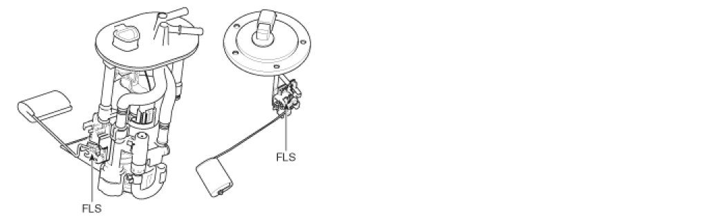
General Description
The Fuel Level Sensor(FLS) measures the fuel level in fuel tank and its information is used to supply the ECM with information regarding the monitoring condition of the EVAP canister purge system for leak detection. If the fuel level sensor is monitored for high or low stuck or difference between voltage of fuel level sensor and voltage deviation of fuel level sensor is exceeds limited value while driving, this is interpreted by the ECM as a fault
DTC Description
Checking output signals of fuel level sender under detecting condition, if the fuel level voltage is high than 10.162V ECM sets P2068.
DTC Detecting Condition
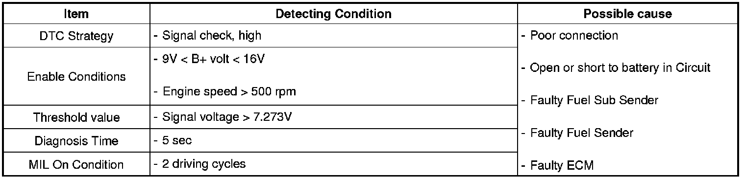
Specification

Diagnostic Circuit Diagram
Monitor Scantool Data
1. Connect scantool to Data Link Connector(DLC).
2. Warm up the engine to normal operating temperature.
3. Monitor the "Fuel Level" parameters on the scantool.

Fig. 1) Normal data of Fuel Level at idle (22%)
4. Are the parameters displayed correctly ?

Terminal and Connector inspection
1. Many malfunctions in the electrical system are caused by poor harness and terminals.
Faults can also be caused by interference from other electrical systems, and mechanical or chemical damage.
2. Thoroughly check connectors for looseness, poor connection, bending, corrosion, contamination, deterioration, or damage.
3. Has a problem been found?

Signal Circuit Inspection
Check short to battery in harness
1. IG "OFF" and disconnect Instrument cluster connector, Fuel Sender A & Fuel Pump Motor connector, and Fuel Sub Sender connector.
2. IG "ON".
3. Measure voltage between total signal terminal of Fuel Sub Sender harness connector and chassis ground.
4. Measure voltage between middle signal terminal of Fuel Sender A & Fuel Pump Motor harness connector and chassis ground.
Specification :Approx. 0V
5. Is the measured voltage within specification ?

Ground Circuit Inspection
Check open in harness
1. IG "OFF" and disconnect Instrument cluster connector and Fuel Sender A & Fuel Pump Motor connector.
2. Measure resistance between ground terminal of Fuel Sender harness connector and Fuel ground terminal of Instrument cluster harness connector.
Specification :Below 1Ohms
3. Is the measured resistance within specification ?

Component Inspection
Check FLS resistance
1. IG "OFF" and Disconnect Fuel Sender & Fuel Pump Motor connector and Fuel Sub Sender connector.
2. Remove these senders from fuel tank and measure the resistance of Fuel sender while lifting up and down the fuel level float.
3. Does the resistance of FLS change as lifting up and down the fuel level float?

Verification of Vehicle Repair
After a repair, it is essential to verifying that the fault has been corrected.
1. Connect scan tool and select "Diagnostic Trouble Codes(DTCs)" mode.
2. Using scantool, Clear DTC.
3. Operate the vehicle within DTC Enable conditions in General information.
4. Are any DTCs present ?
