Clockspring Assembly / Spiral Cable: Service and Repair
WARNING:SAFETY PRECAUTIONS MUST BE FOLLOWED WHEN HANDLING A DEPLOYED AIR BAG ASSEMBLY. AFTER DEPLOYMENT, THE AIR BAG ASSEMBLY SURFACE MAY CONTAIN A SMALL AMOUNT OF SODIUM HYDROXIDE, A BY-PRODUCT OF THE DEPLOYMENT REACTION, THAT IS IRRITATING TO THE SKIN AND EYES. MOST OF THE POWDER ON THE AIR BAG ASSEMBLY IS HARMLESS. AS A PRECAUTION, WEAR GLOVES AND SAFETY GLASSES WHEN HANDLING A DEPLOYED AIR BAG ASSEMBLY, AND WASH YOUR HANDS WITH MILD SOAP AND WATER AFTERWARDS.
WHEN CARRYING A LIVE AIR BAG ASSEMBLY, MAKE SURE THE BAG AND TRIM COVER ARE POINTED AWAY FROM YOU. NEVER CARRY AIR BAG ASSEMBLY BY THE WIRES OR CONNECTOR ON THE UNDERSIDE OF MODULE. IN THE CASE OF AN ACCIDENTAL DEPLOYMENT THE BAG WILL THEN DEPLOY WITH MINIMAL CHANCE OF INJURY. WHEN PLACING A LIVE AIR BAG ASSEMBLY ON A BENCH OR OTHER SURFACE, ALWAYS FACE BAG AND TRIM COVER UP, AWAY FROM THE SURFACE. NEVER REST A STEERING COLUMN ASSEMBLY ON THE STEERING WHEEL WITH THE AIR BAG ASSEMBLY FACE DOWN AND COLUMN VERTICAL. THIS IS NECESSARY SO THAT A FREE SPACE IS PROVIDED TO ALLOW THE AIR BAG ASSEMBLY TO EXPAND IN THE UNLIKELY EVENT OF ACCIDENTAL DEPLOYMENT. OTHERWISE, PERSONAL INJURY COULD RESULT.
NOTE: In the event deployment has occurred, inspect coil assembly wire for any signs of scorching, melting or any other damage due to excessive heat. If the coil has been damaged, replace it.
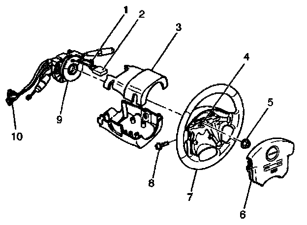
Removal
1. Disable the SRS. Air Bag(s) Arming and Disarming
2. Remove the air bag assembly (6) from steering wheel (7) by removing two bolts (8). Lift air bag assembly out of steering wheel.
3. Disconnect the 2-pin yellow connector (2) and remove air bag assembly.
4. Disconnect horn lead connector (1).
5. Remove the steering wheel attachment nut (5).
6. Move the tires to the straight ahead position before removing the steering wheel and remove wheel with J-29752.
7. Apply a setting mark (4) across the steering wheel and shaft so parts can be reassembled in their original position.
8. Feed wiring though the wheel and remove wheel.
9. Remove the steering lower cover.
10. Remove the driver knee bolster assembly.
11. Remove the steering column cover (3).
12. Disconnect the wiring harness connectors (10) located at the base of steering column.
CAUTION: Never apply force to the steering wheel in the direction of the shaft by using a hammer or other impact tools in an attempt to remove the steering wheel. The steering shaft is designed as an energy absorbing unit.
13. Remove the combination switch assembly with SRS coil (9).
NOTE: SRS coil is a part of combination switch assembly, which cannot be replaced separately. Therefore, be sure not to remove the SRS coil from the combination switch assembly.
Installation
1. Install the combination switch assembly with SRS coil (9).
2. Connect the wiring harness connectors (10) located at the base of steering column.
3. Turn the SRS coil clockwise to full, return about 3 turns and align the neutral mark.
NOTE: Whenever installing the new combination switch with SRS coil, be sure to tear off the lock pin for aligning the neutral position before it is installed to the base of steering column.
CAUTION: When turning the SRS coil clockwise to full, stop turning if resistance is felt. Forced further turning may damage the cable in the SRS coil.
4. Install the steering column cover (3).
CAUTION: When installing the steering column cover, be sure to through each harness as illustrated so that the harnesses starter switch, combination switch and SRS coil may not catch wiring.
5. Install the driver knee bolster assembly.
6. Install the steering lower cover.
7. Install the steering wheel and align the setting marks (4).
6. Tighten the steering wheel fixing nut (5) to the specified torque.
Torque: 34 N.m (25 lb ft)
9. Connect horn lead (1).
10. Connect air bag to wiring harness connector (2).
NOTE: Pass the lead wire through the tabs on the plastic cover (wire protector) of air bag to prevent lead wire from being pinched.
11. Install Air Bag (6) into steering wheel and tighten bolts (8) to specified sequence as figure.
Torque: 8.8 N.m (78 lb in)
CAUTION: Never use the air bag assembly from another vehicle. Use only the air bag assembly for "UE".
12. Enable the SRS. Air Bag(s) Arming and Disarming