Hydraulic Control Assembly - Antilock Brakes: Service and Repair
Hydraulic Control Unit (HCU)
Removal
NOTE:
Removal steps in this procedure may contain installation details.
1 For additional information, refer to Battery Disconnect and Connect Battery Disconnect and Connect
2 For additional information, refer to Cowl Vent Screen Service and Repair
3
WARNING: Make sure to support the vehicle with axle stands.
Raise and support the vehicle.
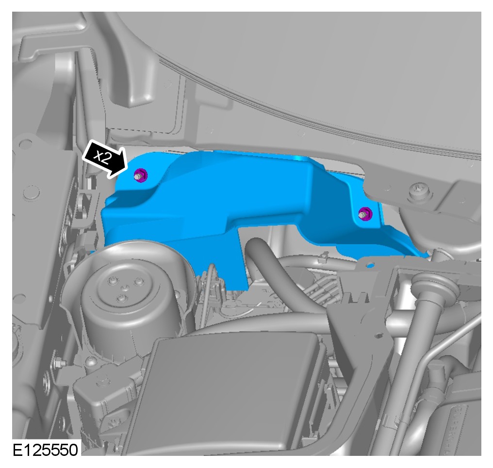
4
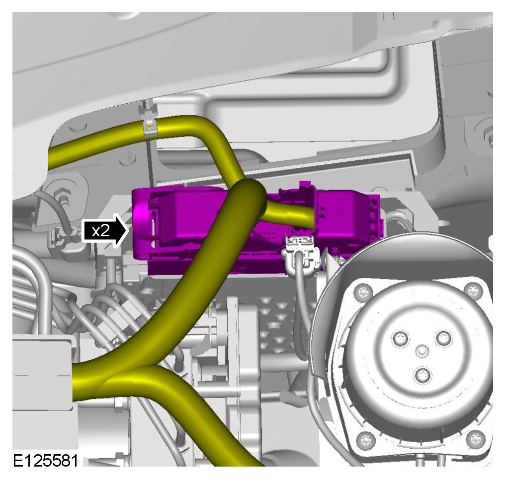
5
CAUTION: Before disconnecting or removing components, ensure the area around the joint faces and connections are clean. Plug open connections to prevent contamination.
NOTE:
RH illustration shown, LH is similar.
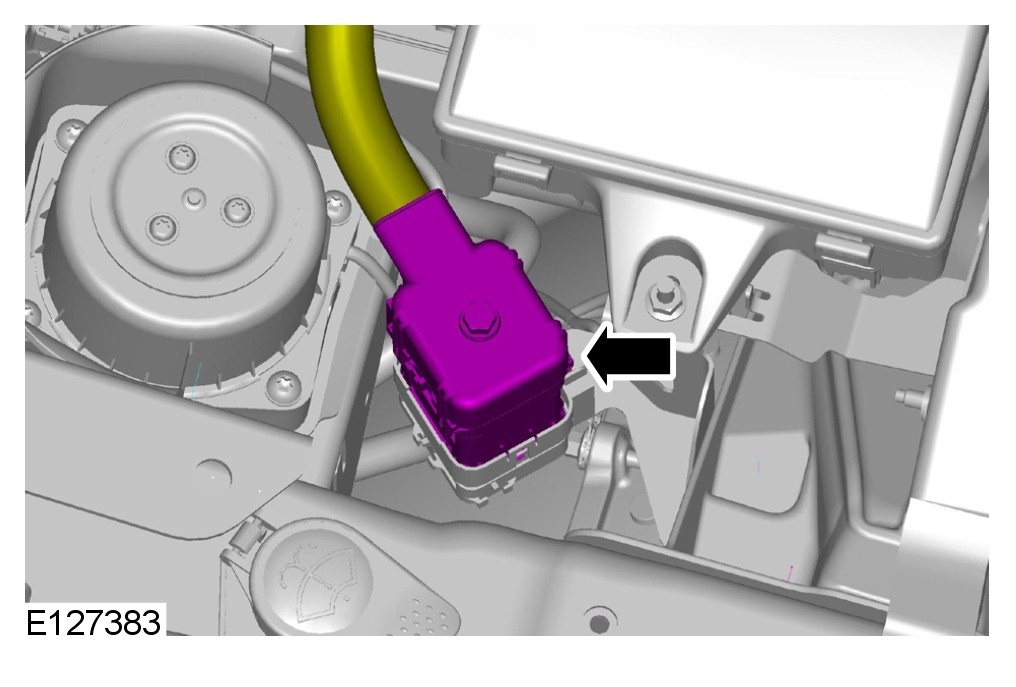
6
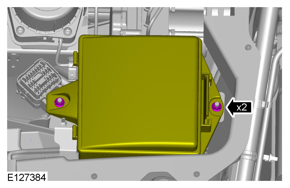
7
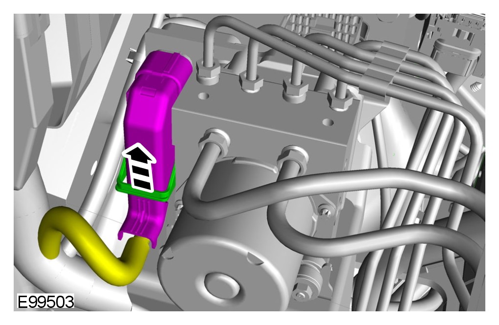
8
NOTE:
Some variation in the illustrations may occur, but the essential information is always correct.
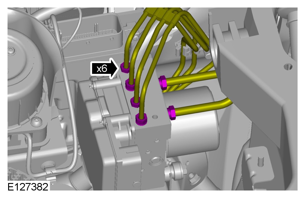
9
CAUTION: Make sure that all openings are sealed. Use new blanking caps.
CAUTION: If brake fluid is spilt on the paintwork, the affected area must be immediately washed down with cold water.
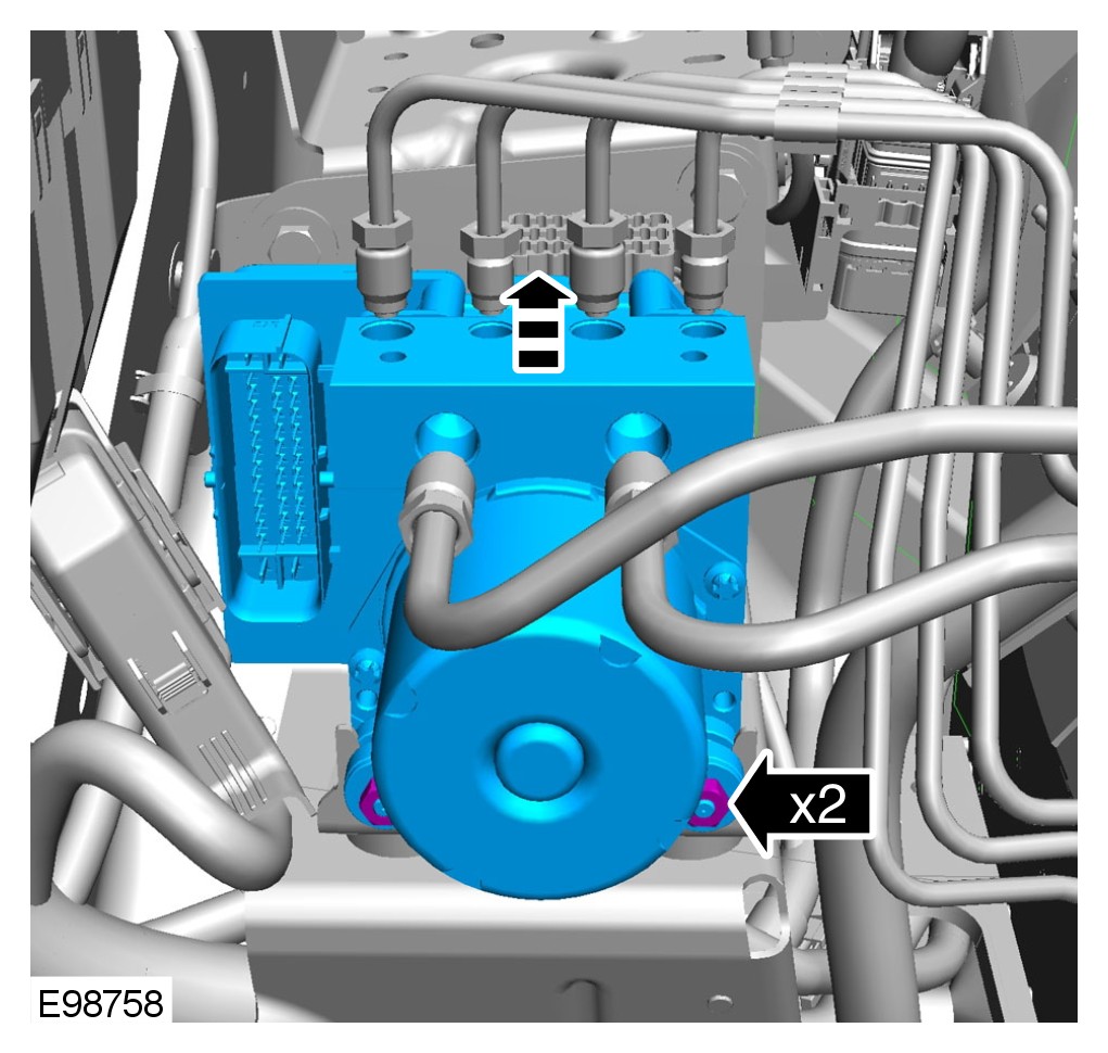
10
NOTE:
Some variation in the illustrations may occur, but the essential information is always correct.
- Loosen but do not remove the 2 nuts.
Installation
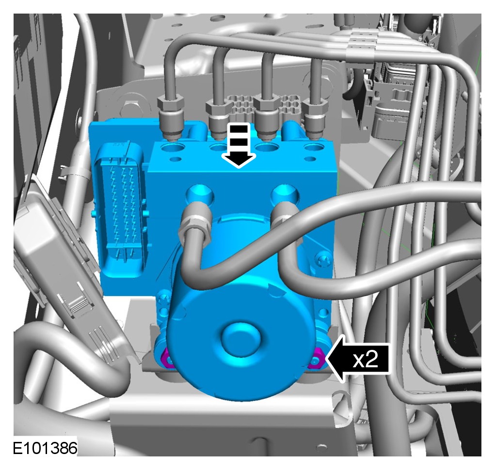
1
CAUTION: If accidentally dropped or knocked install a new hydraulic control unit (HCU) and module.
NOTE:
Make sure the HCU locating grommet is correctly seated in the bracket before installing the ABS module.
NOTE:
Make sure the HCU locating pin is correctly located in the grommet, and the 2 isolators are fully seated in the bracket slots.
NOTE:
Some variation in the illustrations may occur, but the essential information is always correct.
TORQUE: 8 Nm
2
CAUTION: Make sure that the area around the component is clean and free of foreign material.
CAUTION: Make sure that these components are installed to the noted removal position.
NOTE:
Remove and discard the blanking caps.
NOTE:
Some variation in the illustrations may occur, but the essential information is always correct.
TORQUE: 17 Nm
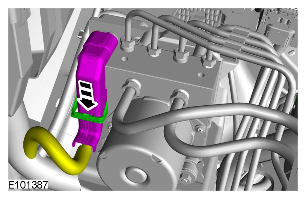
3
NOTE:
Some variation in the illustrations may occur, but the essential information is always correct.
4 TORQUE: 4 Nm
5 TORQUE: 3.5 Nm
6
NOTE:
RH illustration shown, LH is similar.
7 TORQUE: 7 Nm
8 For additional information, refer to Brake System Bleeding Service and Repair
9 For additional information, refer to Cowl Vent Screen Service and Repair
10 For additional information, refer to Battery Disconnect and Connect Battery Disconnect and Connect
11 Using the diagnostic tool, configure the new units using the Programmable Module Installation Routine.