Pinpoint Test C: A Single Power Window Is Inoperative - RF
Glass, Frames and Mechanisms
Pinpoint Tests
Pinpoint Test C: A Single Power Window is Inoperative - RF, Navigator
Refer to Wiring Diagram Set 100, Power Windows for schematic and connector information. Diagrams By Number
Normal Operation
Under normal operation, the RF power window motor microprocessor receives power at all times through circuit SBP04 (GN/RD) and from the accessory delay relay through circuit CBP41 (BU). Ground is provided at all times through circuit GD138 (BK/WH). The master window control switch or passenger window control switch provides a voltage input to the power window motor microprocessor through circuit CPW19 (VT) to operate the RF window down, and voltage input through circuit CPW20 (WH/OG) to operate the RF window up.
This pinpoint test is intended to diagnose the following:
- Fuse(s)
- Wiring, terminals or connectors
- Window control switch
- Front door window regulator motor
PINPOINT TEST C: A SINGLE POWER WINDOW IS INOPERATIVE - RF, NAVIGATOR
NOTE: The RF power window motor is not on the multiplex link.
NOTE: A new RF power window motor will not operate in one-touch up or one-touch down mode until initialized. Refer to Window Motor Initialization .
NOTE: The RF power window motor must be initialized whenever: the motor is removed from the window regulator drum housing, a new motor is installed, a new window regulator is installed, a new window glass is installed, a new top run is installed and any operation in which grease or lubricants are applied to the window system.
-------------------------------------------------
C1 CHECK THE MASTER WINDOW CONTROL SWITCH OPERATION
- Attempt to operate the RH window using the master window control switch.
- Does the RH window operate when using the master window control switch?
Yes
GO to C7.
No
GO to C2.
-------------------------------------------------
C2 CHECK THE POWER TO THE WINDOW MOTOR
- Ignition OFF.
- Disconnect: RF Window Power Window Motor C646.
- Measure the voltage between RF power window motor C646-3, circuit SBP04 (GN/RD) harness side and ground.
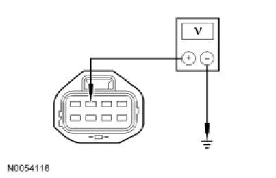
- Is the voltage greater than 10 volts?
Yes
GO to C3.
No
VERIFY the Smart Junction Box (SJB) fuse 4 (30A) is OK. If OK, REPAIR circuit SBP04 (GN/RD) for an open. DE-INITIALIZE, then INITIALIZE the RF power window motor. REFER to Window Motor Initialization . TEST the system for normal operation.
If not OK, REFER to the Wiring Diagrams to identify the possible causes of the circuit short. REPAIR the circuit. DE-INITIALIZE, then INITIALIZE the RF power window motor. REFER to Window Motor Initialization . TEST the system for normal operation.
-------------------------------------------------
C3 CHECK THE RF WINDOW MOTOR DELAYED ACCESSORY FEED
- Ignition ON.
- Measure the voltage between RF power window motor C646-2, circuit CBP41 (BU) harness side and ground.
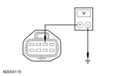
- Is the voltage greater than 10 volts?
Yes
GO to C4.
No
VERIFY SJB fuse 41 (15A) is OK. If OK, REPAIR circuit CBP41 (BU) for an open. DE-INITIALIZE, then INITIALIZE the RF power window motor. REFER to Window Motor Initialization . TEST the system for normal operation.
If not OK, REFER to the Wiring Diagrams to identify the possible causes of the circuit short. REPAIR the circuit. DE-INITIALIZE, then INITIALIZE the RF power window motor. REFER to Window Motor Initialization . TEST the system for normal operation.
-------------------------------------------------
C4 CHECK THE RF MOTOR GROUNDS
- Ignition OFF.
- Open the front door to disable delayed accessory power.
- Measure the resistance between RF power window motor C646-8, circuit GD138 (BK/WH), harness side and ground.
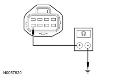
- Is the resistance less than 5 ohms?
Yes
GO to C5.
No
REPAIR circuit GD138 (BK/WH) for an open. DE-INITIALIZE, then INITIALIZE the RF power window motor. REFER to Window Motor Initialization . TEST the system for normal operation.
-------------------------------------------------
C5 CHECK THE FRONT WINDOW SWITCH TO RF MOTOR FEEDS
- Disconnect: Master Window Control Switch C535A.
- Measure the resistance between RF power window motor C646, harness side and master window control switch C535A, harness side using the following chart:
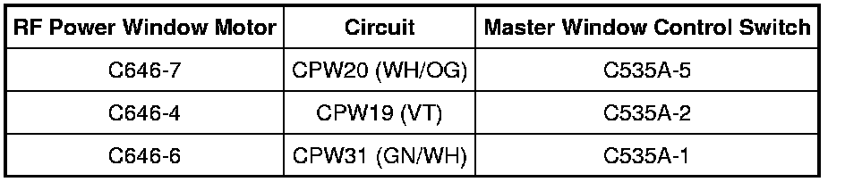
- Is the resistance less than 5 ohms?
Yes
GO to C6.
No
REPAIR circuit CPW20 (WH/OG), CPW19 (VT) or CPW31 (GN/WH) for an open. DE-INITIALIZE, then INITIALIZE the RF power window motor. REFER to Window Motor Initialization . TEST the system for normal operation.
-------------------------------------------------
C6 CHECK THE MASTER WINDOW CONTROL SWITCH
- Carry out the master window control switch component test.
- Did the master window control switch pass the component test?
Yes
INSTALL a new RF power window motor. REFER to Window Regulator Motor - Front Door Window Regulator Motor - Front Door. INITIALIZE the RF door window motor. REFER to Window Motor Initialization . TEST the system for normal operation.
No
INSTALL a new master window control switch. REFER to Window Control Switch Service and Repair. TEST the system for normal operation.
-------------------------------------------------
C7 CHECK CIRCUIT CBP41 (BU) FOR AN OPEN
- Disconnect: Passenger Window Control Switch C648.
- Ignition ON.
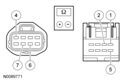
- Measure the voltage between passenger window control switch C648-2, circuit CBP41 (BU), harness side and ground.
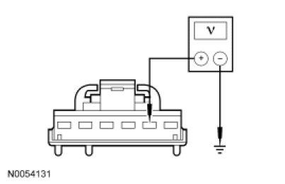
- Is the voltage greater than 10 volts?
Yes
GO to C8.
No
REPAIR circuit CBP41 (BU) for an open. DE-INITIALIZE, then INITIALIZE the RF power window motor. REFER to Window Motor Initialization . TEST the system for normal operation.
-------------------------------------------------
C8 CHECK CIRCUIT GD138 (BK/WH) FOR AN OPEN
- Ignition OFF.
- Measure the resistance between passenger front window control switch C648-6, circuit GD138 (BK/WH), harness side and ground.
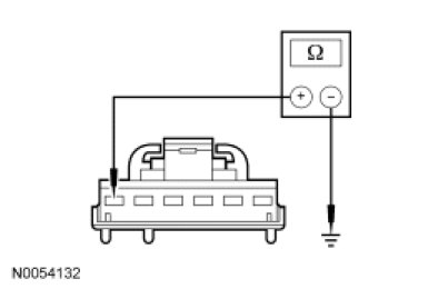
- Is the resistance less than 5 ohms?
Yes
GO to C9.
No
REPAIR circuit GD138 (BK/WH) for an open. DE-INITIALIZE, then INITIALIZE the RF power window motor. REFER to Window Motor Initialization . TEST the system for normal operation.
-------------------------------------------------
C9 CHECK THE FRONT WINDOW SWITCH TO RF MOTOR FEEDS
- Measure the resistance between RF power window motor C646, harness side and passenger window control switch, harness side using the following chart:
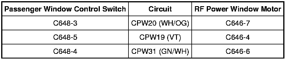
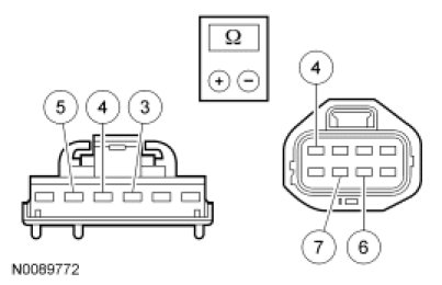
- Is the resistance less than 5 ohms on all circuits?
Yes
INSTALL a new passenger window control switch. REFER to Window Control Switch Service and Repair. TEST the system for normal operation.
No
REPAIR circuit CPW20 (WH/OG), CPW19 (VT) or CPW31 (GN/WH) for an open. DE-INITIALIZE, then INITIALIZE the RF power window motor. REFER to Window Motor Initialization . TEST the system for normal operation.
-------------------------------------------------