I - Charts
Seat Belt Warning Light: Seat belt warning light does not work normally.NOTE: This troubleshooting procedure requires the use of scan tool MB991502 and SWS monitor kit MB991862. For details on how to use the SWS monitor, refer to "How to use SWS monitor."
Seat Belt Warming Light Circuit Part 1:
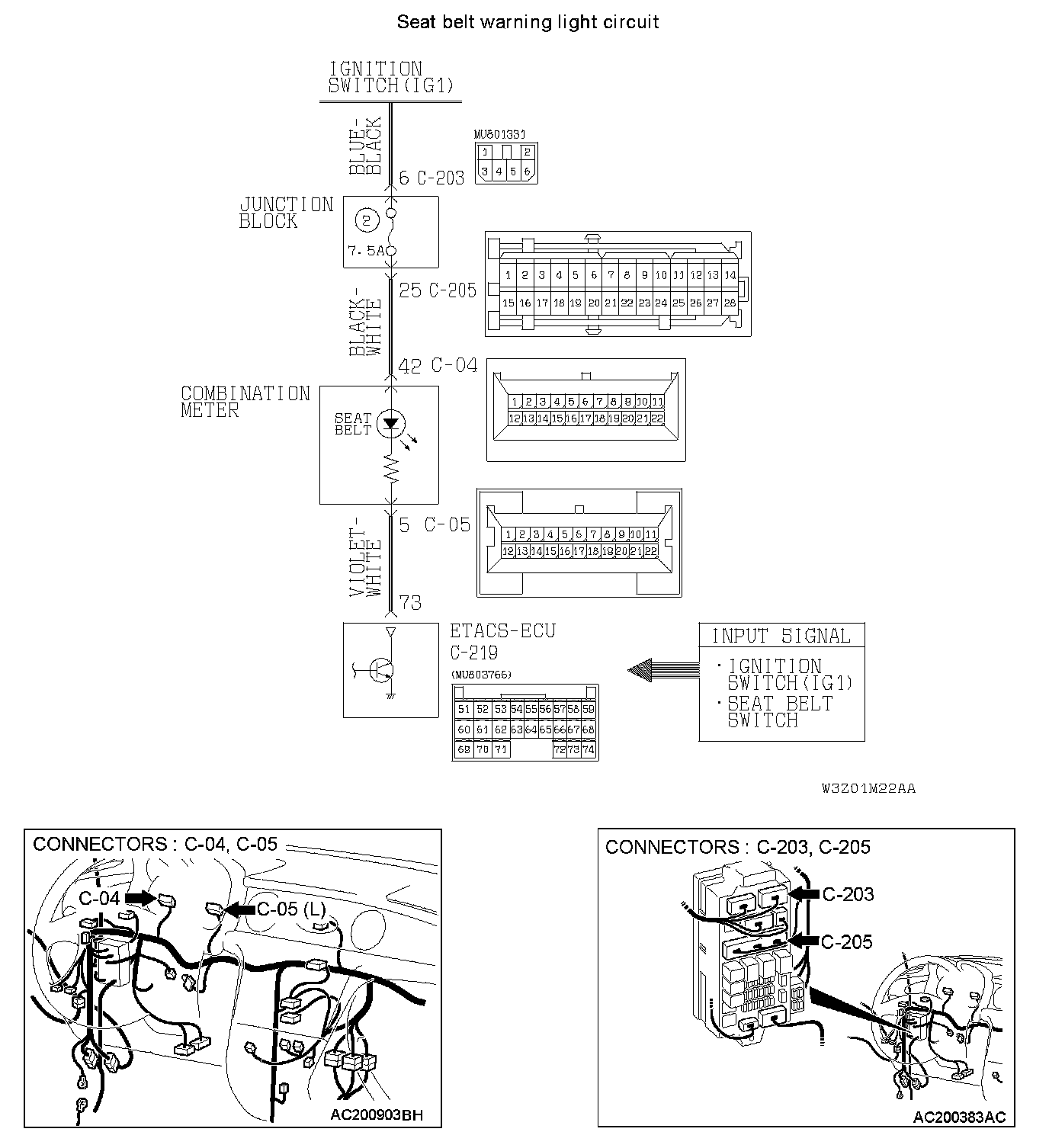
Seat Belt Warming Light Circuit Part 2:
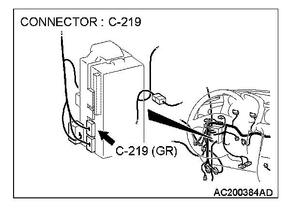
CIRCUIT OPERATION
- The ETACS-ECU operates the seat belt warning light according to the following switch signals:
- Ignition switch (IG1)
- Driver's seat belt switch
- If the driver turn the ignition switch to the "ON" position without fastening the seat belt, the seat belt warning light illuminates.
TECHNICAL DESCRIPTION (COMMENT)
If the seat belt warning light does not illuminate, the input circuit, the combination meter (seat belt warning light bulb or printed-circuit board) or the ETACS-ECU may be defective.
TROUBLESHOOTING HINTS
- The driver's side seat belt switch may be defective
- The combination meter (seat belt warning light bulb or printed-circuit board) may be defective
- The ETACS-ECU may be defective
- The wiring harness or connectors may have loose, corroded, or damaged terminals, or terminals pushed back in the connector
Required Special Tools:
- MB991223: Harness Set
- MB991502: Scan Tool (MUT-II)
- MB991862: SWS monitor kit
STEP 1. Use scan tool MB991502 to select "ECU COMM CHECK" on the SWS monitor display.
Check the ETACS-ECU.
CAUTION: To prevent damage to scan tool MB991502, always turn the ignition switch to the "LOCK" (OFF) position before connecting or disconnecting scan tool MB991502.
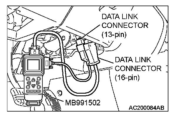
1. Connect scan tool MB991502 to the data link connector (16-pin).
2. Connect SWS monitor kit MB991862 to the data link connector (13-pin).
3. When the ignition switch is turned to the "ON" position.
4. Operate the scan tool MB991502 according to the procedure below to display "ECU COMM CHECK."
1. Select "SYSTEM SELECT."
2. Select "SWS."
3. Select "SWS MONITOR."
4. Select "ECU COMM CHECK."
5. Scan tool MB991502 should show "OK" on the "ECU COMM CHECK" menu for the "ETACS ECU" menu.
Q: Is "OK" displayed on the "ETACS ECU" menu?
YES: Go to Step 2.
NO: Refer to Inspection Procedure A-3 "Communication with ETACS-ECU is not possible."
STEP 2. Check the input signal by using "DATA LIST" menu of the SWS monitor.
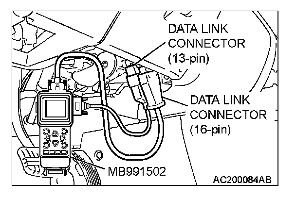
Turn the ignition switch to the "ON" position before checking input signals from the ignition switch (IG1).
Operate the scan tool MB991502 according to the procedure below to display "ETACS ECU."
1. Select "SYSTEM SELECT."
2. Select "SWS."
3. Select "SWS MONITOR."
4. Select "DATA LIST."
5. Select "ETACS ECU."

Check that normal conditions are displayed on the items described in the table.
Q: Is normal condition displayed "IG SW (IG1)"?
YES: Go to Step 3.
NO: Refer to Inspection Procedure N-2 "ETACS-ECU does not receive a signal from the ignition switch (IG1)."
STEP 3. Check the input signal by using the pulse check mode of the monitor.
Check input signal from the driver's side seat belt switch.
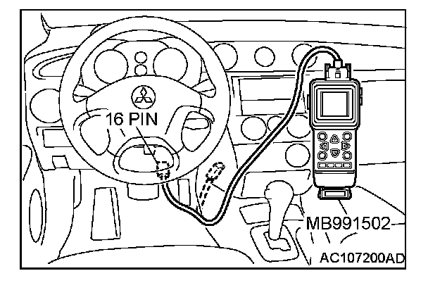
Operate the scan tool MB991502 according to the procedure below to display "PULSE CHECK."
1. Select "SYSTEM SELECT."
2. Select "SWS."
3. Select "PULSE CHECK."
- When the driver's seat belt is fastened, check if scan tool MB991502 sounds or not.
Q: Does scan tool MB991502 sound when the driver's side seat belt is fastened?
YES: Go to Step 4.
NO: Refer to Inspection Procedure O-3 "ETACS-ECU does not receive a signal from the driver's side seat belt switch."
STEP 4. Check at ETACS-ECU connector C-219 in order to check the ground circuit to the seat belt warning light circuit.
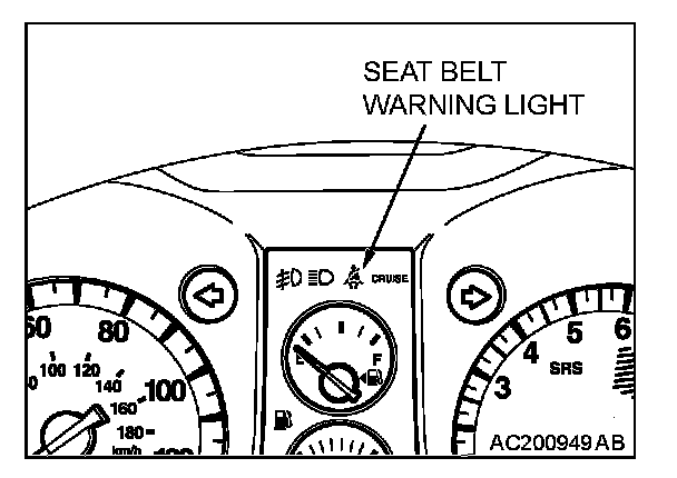
1. Disconnect ETACS-ECU connector C-219, and measure at the wiring harness side.
2. Turn the ignition switch to the "ON" position.
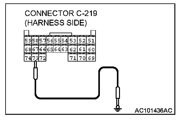
3. Connect terminal 73 to ground.
Q: Does the seat belt warning light illuminate?
YES: Replace the ETACS-ECU. Verify that the seat belt warning light illuminates normally.
NO: Go to Step 5.
STEP 5. Check the combination meter (printed-circuit board).
1. Remove the combination meter.
CAUTION: Connect the positive terminal of the megohmmeter to terminal 42 of the C-04 connector and the negative terminal of the megohmmeter to terminal 5 of the C-05 connector. The megohmmeter will show an infinity reading if the positive and negative terminals of the megohmmeter are reversed.
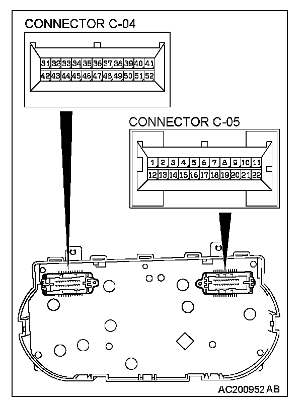
2. Measure the resistance value between connector C-04 terminal 42 and connector C-05 terminal 5.
- The resistance should equal 2 ohms or less.
Q: Is the measured resistance 2 ohms or less?
YES: Go to Step 6.
NO: Repair or replace the combination meter (printed circuit board). Verify that the seat belt warning light illuminates normally.
STEP 6. Check the ignition switch (IG1) circuit to the combination meter. Test at combination meter connector C-04.
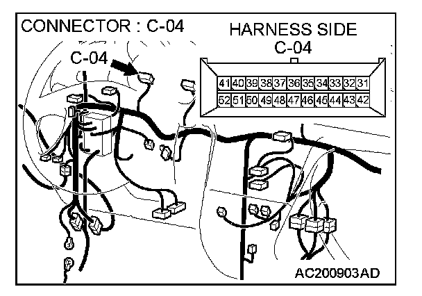
1. Disconnect combination meter connector C-04 and measure the voltage available at the wiring harness side of the connector.
2. Turn the ignition switch to the "ON" position.
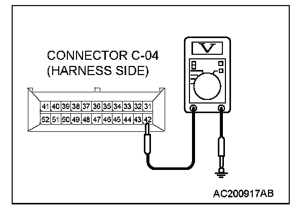
3. Measure the voltage between terminal 42 and ground.
- The voltage should equal approximately 12 volts (battery positive voltage).
Q: Is the measured voltage approximately 12 volts (battery positive voltage)?
YES: Go to Step 9.
NO: Go to Step 7.
STEP 7. Check combination meter connector C-04 for loose, corroded or damaged terminals, or terminals pushed back in the connector.
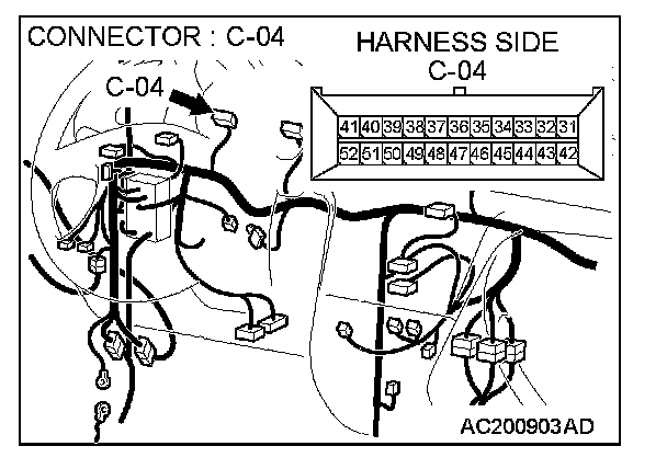
Q: Is combination meter connector C-04 in good condition?
YES: Go to Step 8.
NO: Repair or replace the damaged components). Refer to Harness Connector Inspection. Verify that the seat belt warning light illuminates normally.
STEP 8. Check the wiring harness between combination meter connector C-04 (terminal 42) and the ignition switch (IG1).
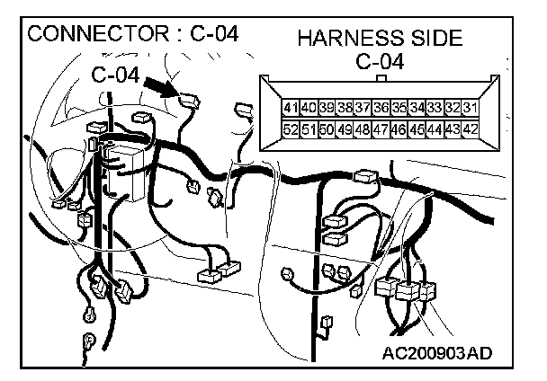
NOTE: Also check junction block connectors C-203 and C-205 for loose, corroded, or damaged terminals, or terminals pushed back in the connector. If junction block connector C-203 and C-205 is damaged, repair or replace the damaged component(s) as described in Harness Connector Inspection.
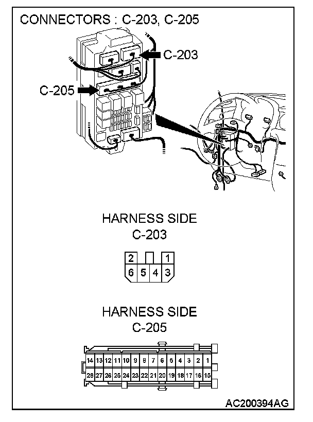
Q: Is the wiring harness between combination meter connector C-04 (terminal 42) and the ignition switch (IG1) in good condition?
YES: No action is necessary and testing is complete.
NO: The wiring harness may be damaged or the connector(s) may have loose, corroded or damaged terminals, or terminals pushed back in the connector. Repair the wiring harness as necessary. Verify that the seat belt warning light illuminates normally.
STEP 9. Check combination meter connector C-05 and ETACS-ECU connector C-219 for loose, corroded or damaged terminals, or terminals pushed back in the connector.
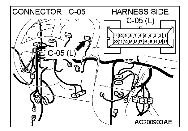
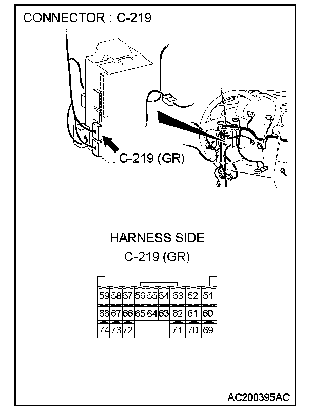
Q: Are combination meter connector C-05 and ETACS-ECU connector C-219 in good condition?
YES: Go to Step 10.
NO: Repair or replace the damaged components). Refer to Harness Connector Inspection. Verify that the seat belt warning light illuminates normally.
STEP 10. Check the wiring harness between combination meter connector C-05 (terminal 5) and ETACS-ECU connector C-219 (terminal 73).
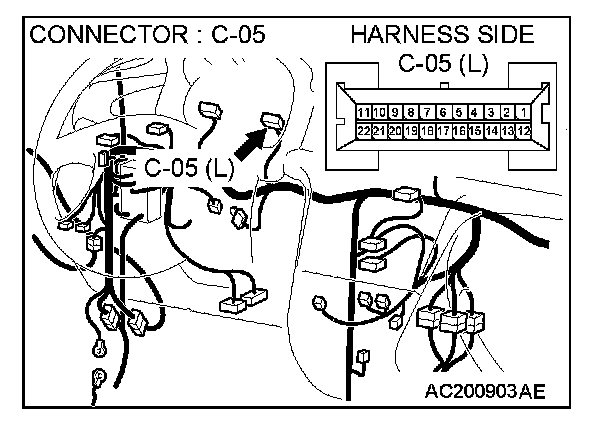
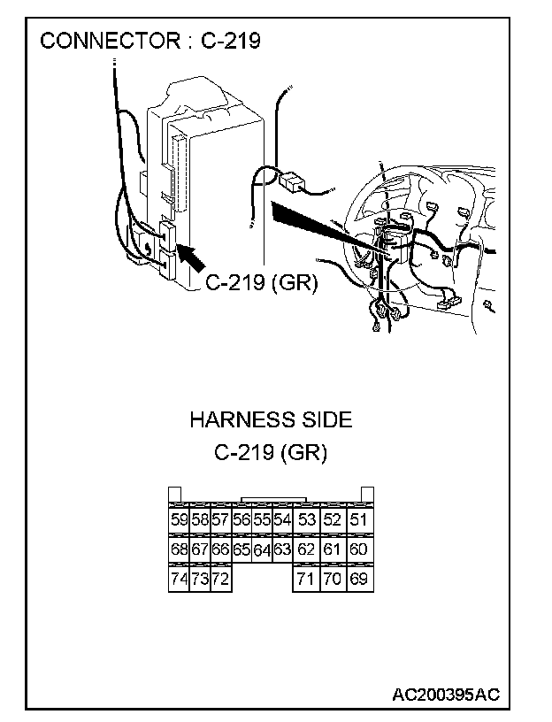
Q: Is the wiring harness between combination meter connector C-05 (terminal 5) and ETACS-ECU connector C-219 (terminal 73) in good condition?
YES: No action is necessary and testing is complete.
NO: The wiring harness may be damaged or the connector(s) may have loose, corroded or damaged terminals, or terminals pushed back in the connector. Repair the wiring harness as necessary. Verify that the seat belt warning light illuminates normally.