Inspection Procedure L-7
INSPECTION PROCEDURE L-7: Interior Light: When the interior light "ON" or "OFF" switch is operated, the dome lights do not illuminate or go out normally.NOTE: This troubleshooting procedure requires the use of scan tool MB991958 and SWS monitor kit MB991813. For details on how to use the SWS monitor, refer to "How to use SWS monitor."
CIRCUIT OPERATION
The ETACS-ECU illuminates and turn off the dome lights, based on the signal from the overhead console assembly (ON and OFF switches).
TECHNICAL DESCRIPTION (COMMENT)
If the dome lights do not illuminate or go off normally, the overhead console assembly (ON and OFF switches) or the ETACS-ECU may be defective.
TROUBLESHOOTING HINTS
- Trouble in input signal system
- The wiring harness or connectors may have loose, corroded, or damaged terminals, or terminals pushed back in the connector
- The ETACS-ECU may be defective
DIAGNOSIS
Required Special Tools:
- MB991223: Harness Set
- MB992006: Extra Fine Probe
- MB991958: Scan Tool (M.U.T.-III Sub Assembly)
- MB991824: V.C.I.
- MB991827: M.U.T.-III USB Cable
- MB991910: M.U.T.-III Main Harness A
- MB991813: SWS Monitor Kit
- MB991806: SWS Monitor Cartridge
- MB991812: SWS Monitor Harness (For Column-ECU)
- MB991822: Probe Harness
STEP 1. Check the operation of the dome lights. When the dome light switch is set to "DOOR" position, and any door is opened, check that the dome lights illuminate.
Q: Are the dome lights in good condition?
The dome lights illuminate normally. : Go to Step 2.
All the dome lights do not illuminate. : Refer to Inspection Procedure L-1 "The dome light does not illuminate and go out normally."
One of the dome lights does not illuminate. : Refer to Inspection Procedure L-2 "The dome lights, map lights, rear personal lights, cargo area light or front door lights do not illuminate or go out normally."
STEP 2. Use scan tool MB991958 to select "ECU COMM CHK" on the SWS monitor display.
Check the ETACS-ECU.
CAUTION: To prevent damage to scan tool MB991958, always turn the ignition switch to the "LOCK" (OFF) position before connecting or disconnecting scan tool MB991958. Connect special tool MB991910 before connecting special tool MB991812. Be sure to connect special tool MB991806 after turning on special tool MB991824.
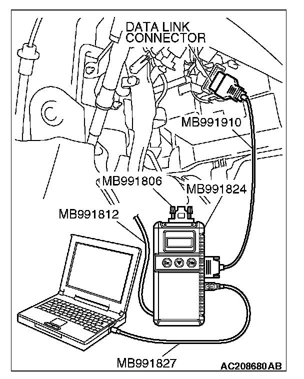
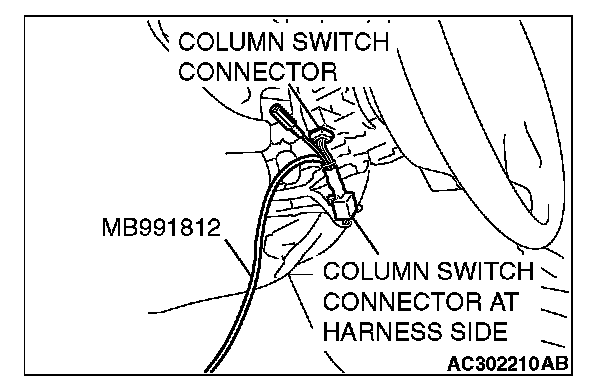
1. Connect the special tool. Refer to "How to connect SWS monitor."
2. Turn the ignition switch to the "LOCK" (OFF) position.
3. Operate scan tool MB991958 according to the procedure below to display "ECU COMM Check."
a. Select "Interactive Diagnosis."
b. Select "System select."
c. Select "SWS."
d. Select "SWS MONITOR."
e. Select "ECU COMM Check."
4. Scan tool MB991958 should show "OK" on the "ECU COMM Check" menu for the "ETACS ECU" menu.
Q: Is "OK" displayed for the "ETACS ECU" menu?
YES: Go to Step 3.
NO: Refer to Inspection Procedure A-3 "Communication with the ETACS-ECU is not possible."
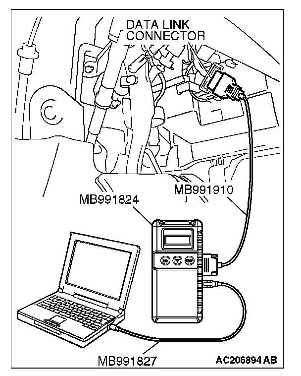
STEP 3. Check the input signal (by using the pulse check mode of the monitor).
Check the input signal from the overhead console assembly (ON and OFF switches).
1. Operate scan tool MB991958 according to the procedure below to display "Pulse check."
a. Select "Interactive Diagnosis."
b. Select "System select."
c. Select "SWS."
d. Select "Pulse Checking."
Q: When the switch is operated, does scan tool MB991958 sound?
YES: Replace the ETACS-ECU. When the ON and OFF switches are operated, check that the dome lights illuminate and go off normally.
NO: Refer to Inspection Procedure P-13 "The interior light "on" or "off" switch signal is not sent to the ETACS-ECU."