Inspection Procedure 3
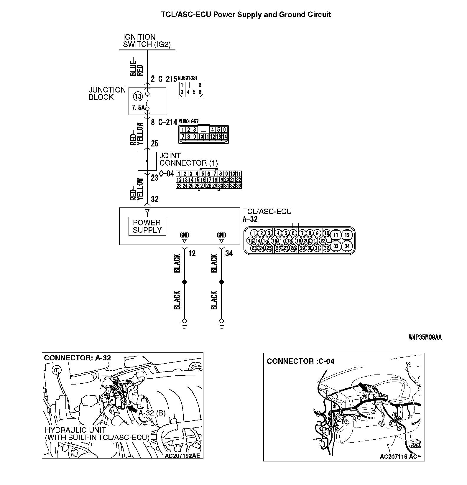
INSPECTION PROCEDURE 3: TCL/ASC-ECU power supply systemTCL/ASC-ECU Power Supply and Ground Circuit (Part 1):
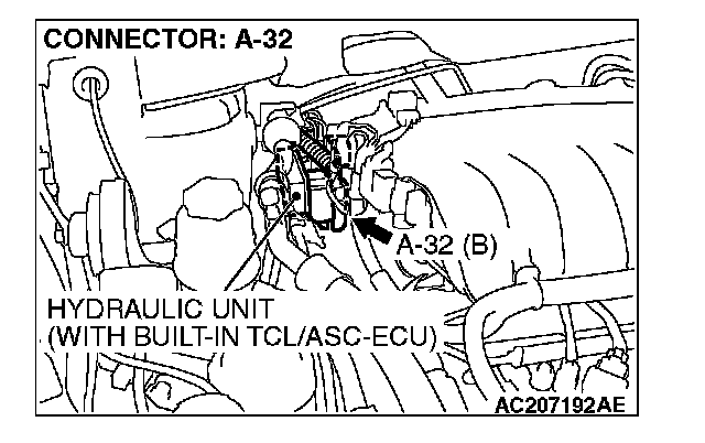
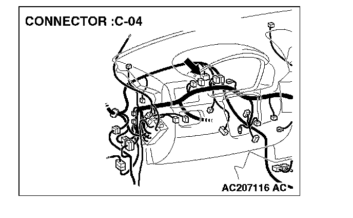
TCL/ASC-ECU Power Supply and Ground Circuit (Part 2):
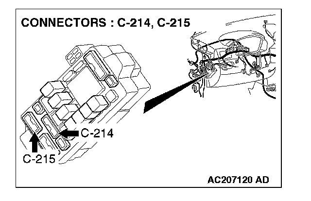
CIRCUIT OPERATION
^ The TCL/ASC-ECU is energized by the ignition switch (IG2) through multi-purpose fuse 13 and the TCL/ASC-ECU terminal 32.
^ If the power supply to the TCL/ASC-ECU has failed, scan tool MB991958 will not be able to communicate with it.
TROUBLESHOOTING HINTS (The most likely causes for this case:)
^ Damaged wiring harness or connector
^ Defective battery
^ Charging system failed
^ Malfunction of the hydraulic unit (integrated with TCL/ASC-ECU)
DIAGNOSIS
Required Special Tools:
^ MB991958: Scan Tool (M.U.T.-III Sub Assembly)
- MB991824: Vehicle Communication Interface (V.C.I.)
- MB991827: M.U.T.-III USB Cable
- MB991910: M.U.T.-III Main Harness A
^ MB991952: ABS Check Harness
STEP 1. Measure the voltage at TCL/ASC-ECU connector A-32.
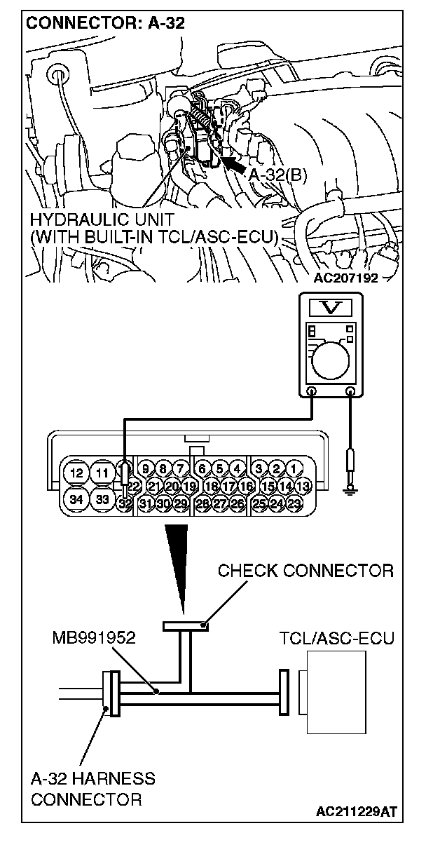
(1) Disconnect the connector A-32, and connect special tool ABS Check Harness (MB991952) to the wiring harness-side connector.
NOTE: Do not connect special tool ABS Check Harness (MB991952) to the TCL/ASC-ECU.
(2) Turn the ignition switch to the "ON" position.
(3) Measure the voltage between terminal 32 and ground. It should measure approximately 12 volts (battery positive voltage).
Q: Is battery positive voltage (approximately 12 volts) present?
YES: Go to Step 3.
NO: Go to Step 2.
STEP 2. Check the following connectors.
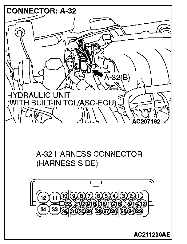
^ TCL/ASC-ECU connector A-32
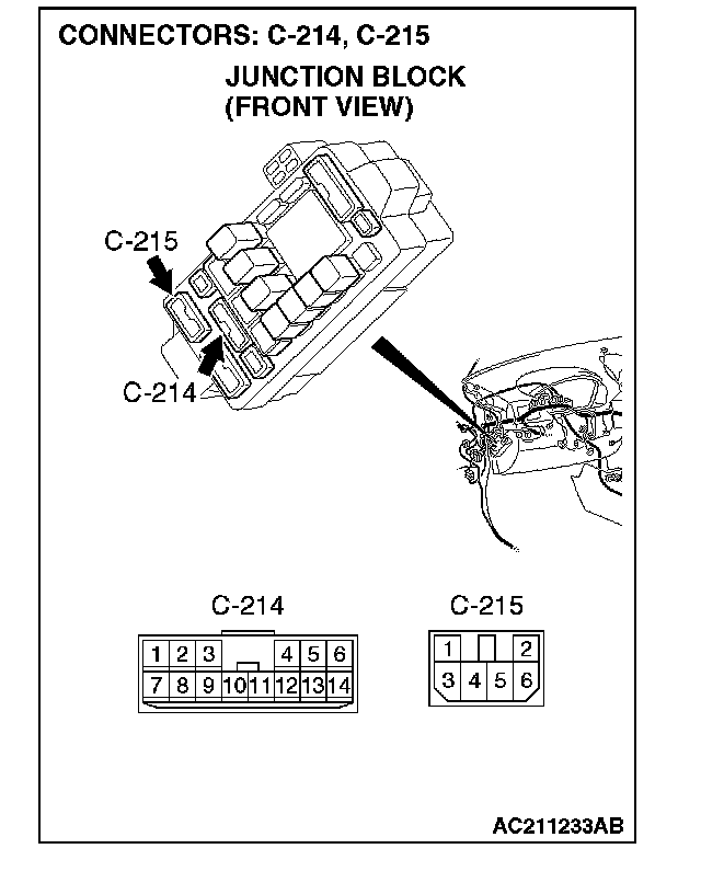
^ Junction block connectors C-214 and C-215
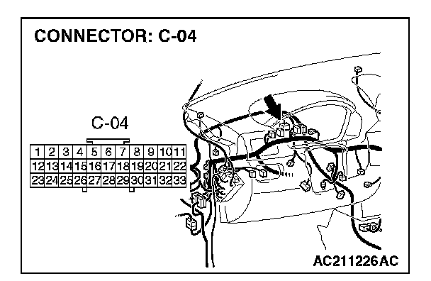
^ Joint connector (1) C-04
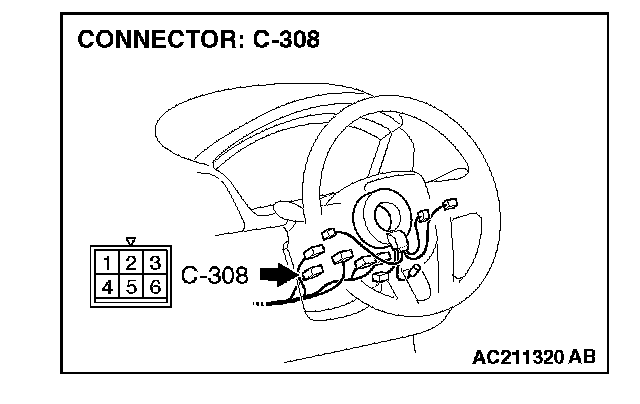
^ Ignition switch connector C-308
Check the connectors, for loose, corroded or damaged terminals, or terminals pushed back in the connector.
Q: Are the connectors and terminals in good condition?
YES: An open or short circuit may be present in the power supply line to the TCL/ASC-ECU. Repair the wiring harness between TCL/ASC-ECU connector A-32 terminal 32 and ignition switch connector C-308 terminal 4. Go to Step 8.
NO: Repair or replace the damaged component(s). Then go to Step 8.
STEP 3. Measure the resistance at TCL/ASC-ECU connector A-32.
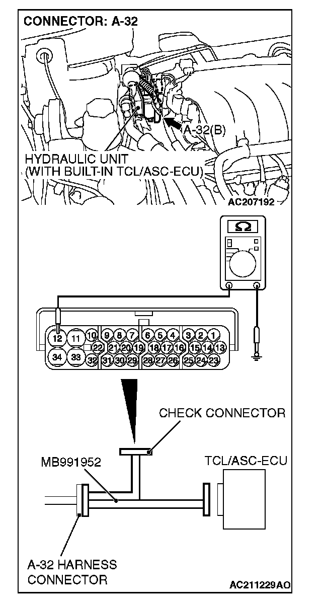
(1) Disconnect the connector A-32, and connect special tool ABS Check Harness (MB991952) to the wiring harness-side connector.
NOTE: Do not connect special tool ABS Check Harness (MB991952) to the TCL/ASC-ECU.
(2) Measure the resistance between terminal 12, 34 and ground. It should be 2 ohms or less.
Q: Is the measured resistance 2 ohms or less?
YES: Go to Step 5.
NO: Go to Step 4.
STEP 4. Check TCL/ASC-ECU connector A-32 for loose, corroded or damaged terminals, or terminals pushed back in the connector.
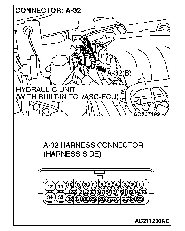
Q: Are the connectors and terminals in good condition?
YES: An open circuit may be present in the ground circuit. Repair the wiring harness between TCL/ASC-ECU connector A-32 terminals 12, 34 and the body ground. Then go to Step 8.
NO: Repair or replace the damaged component(s). Then go to Step 8.
STEP 5. Check the battery.
Check the battery.
Q: Is the battery in good condition?
YES: Go to Step 6.
NO: Charge or replace the battery. Then go to Step 8.
STEP 6. Check the charging system.
Check the charging system.
Q: Is the charging system in good condition?
YES: Go to Step 7.
NO: Repair or replace the charging system component(s).Then go to Step 8.
STEP 7. Retest the system.
Q: Can the TCL/ASC-ECU communicate with the scan tool (M.U.T.-III Sub Assembly)?
YES: It can be assumed that this malfunction is intermittent. Refer to How to Use Troubleshooting/Inspection Service Points - How to Cope with Intermittent Malfunction. Initial Inspection and Diagnostic Overview
NO: Replace the TCL/ASC-ECU. Then go to Step 8.
STEP 8. Retest the system.
Q: Can the TCL/ASC-ECU communicate with the scan tool (M.U.T.-III Sub Assembly)?
YES: The procedure is complete.
NO: Go to Step 1.