Inspection Procedure 5
INSPECTION PROCEDURE 5: G and yaw rate sensor power supply supply system
CIRCUIT OPERATION
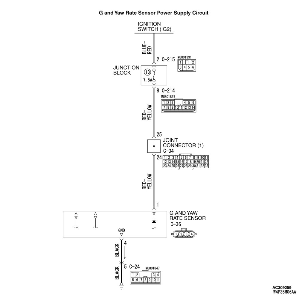
- The G and yaw rate sensor is energized by the ignition switch (IG2) through multi-purpose fuse No.13 and the G and yaw rate sensor terminal 1.
- If the power supply to the G and yaw rate sensor has failed, TCL/ASC-ECU related DTC U1105 is set.
TROUBLESHOOTING HINTS (The most likely causes for this case:)
- Damaged wiring harness or connector
- Defective battery
- Charging system failed
- Malfunction of the G and yaw rate sensor
DIAGNOSIS
Required Special Tools:
- MB991958: Scan Tool (M.U.T.-III Sub Assembly)
- MB991824: Vehicle Communication Interface (V.C.I.)
- MB991827: M.U.T.-III USB Cable
- MB991910: M.U.T.-III Main Harness A
- MB991952: ABS Check Harness
STEP 1. Measure the voltage at G and yaw rate sensor connector C-36.
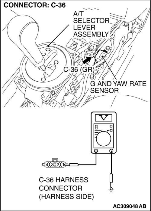
(1)Disconnect the G and yaw rate sensor connector C-36, and measure at the harness side connector.
(2)Turn the ignition switch to the "ON" position.
(3)Measure the voltage between terminal 1 and body ground.
- Voltage should measure battery positive voltage (approximately 12 volts).
Q. Is battery positive voltage (approximately 12 volts) present?
YES Go to Step 3.
NO Go to Step 2.
STEP 2. Check the following connectors.
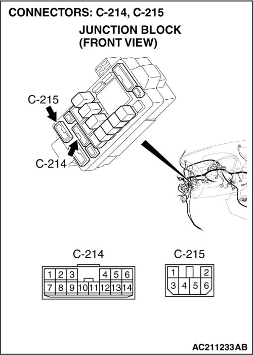
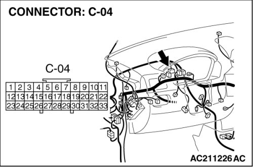
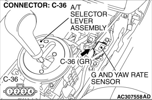
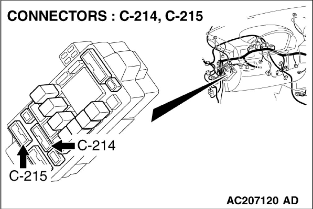
- Junction block connectors C-214 and C-215
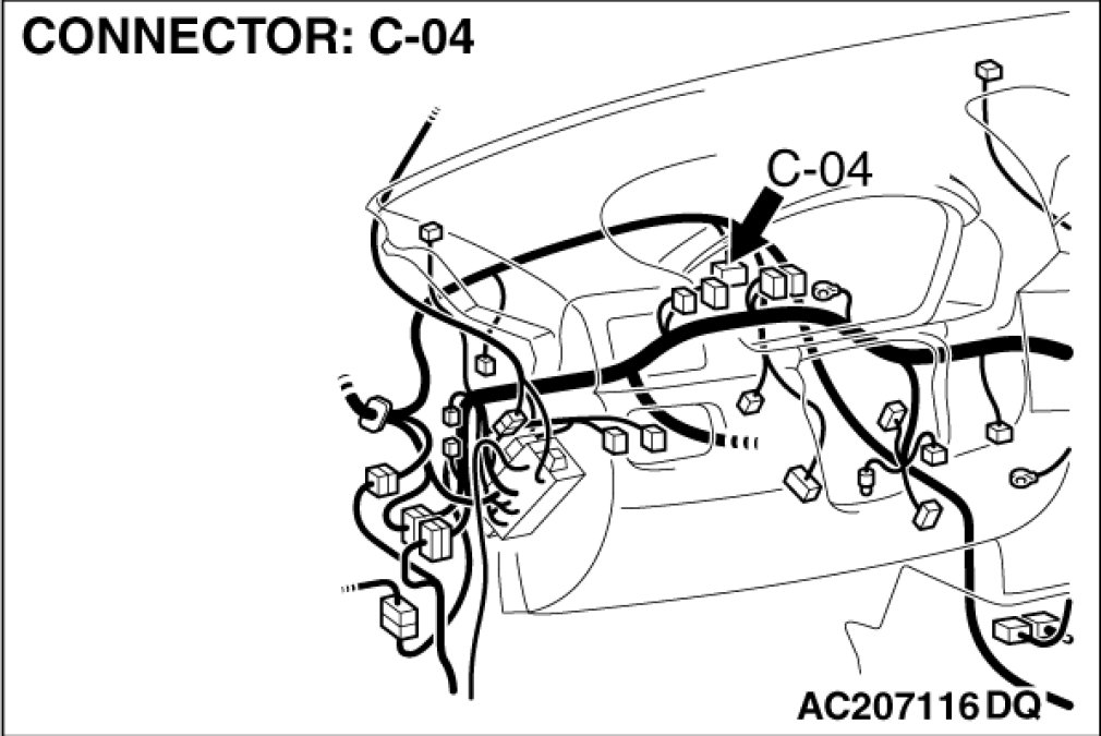
- Joint connector (1) C-04
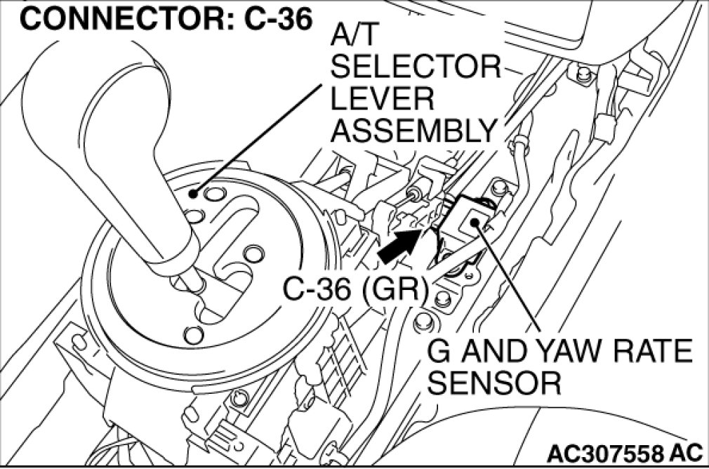
- G and yaw rate sensor connector C-36
Check the connectors, for loose, corroded or damaged terminals, or terminals pushed back in the connector.
Q. Are the connectors and terminals in good condition?
YES An open or short circuit may be present in the power supply line to the G and yaw rate sensor. Repair the wiring harness between G and yaw rate sensor connector C-36 terminal 1 and ignition switch connector C-308 terminal 4. Go to Step 7.
NO Repair or replace the damaged component(s). Harness Connector Inspection. Then go to Step 7.
STEP 3. Measure the resistance at G and yaw rate sensor connector C-36.
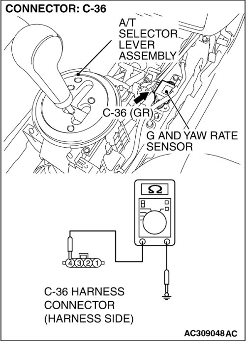
(1)Disconnect the G and yaw rate sensor connector C-36, and measure at the harness side connector.
(2)Measure the resistance between terminal 4 and body ground.
Q. Is the measured resistance 2 ohms or less?
YES Go to Step 5.
NO Go to Step 4.
STEP 4. Check G and yaw rate sensor connector C-36 for loose, corroded or damaged terminals, or terminals pushed back in the connector.
Q. Are the connectors and terminals in good condition?
YES An open circuit may be present in the ground circuit. Repair the wiring harness between G and yaw rate sensor connector C-36 terminals 4 and the body ground. Then go to Step 7.
NO Repair or replace the damaged component(s). Harness Connector Inspection. Then go to Step 7.
STEP 5. Check the battery.
Check the battery Battery Test).
Q. Is the battery in good condition?
YES Go to Step 6.
NO Charge or replace the battery. Then go to Step 7.
STEP 6. Check the charging system.
Check the charging system Initial Inspection and Diagnostic Overview).
Q. Is the charging system in good condition?
YES Replace the G and yaw rate sensor (Refer to Service and Repair). Then go to Step 7.
NO Repair or replace the charging system component(s).Then go to Step 7.
STEP 7. Using scan tool MB991958, read the TCL/ASC diagnostic trouble code.
CAUTION:
To prevent damage to scan tool always turn the ignition switch to "LOCK" (OFF) position before connecting or disconnecting scan tool.
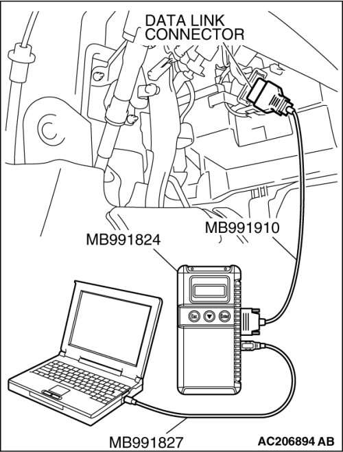
(1)Connect scan tool MB991958 to the data link connector.
(2)Turn the ignition switch to the "ON" position.
(3)Read the TCL/ASC diagnostic trouble code.
Q. Is the DTC U1105 (current trouble) set?
YES Diagnose the TCL/ASC by referring to U1105.
NO The procedure is complete.