Inspection Procedure 9
INSPECTION PROCEDURE 1: When the Ignition Switch is Turned to the "ON" Position (Engine Stopped), the "TCL OFF" Indicator Light does not Illuminate. INSPECTION PROCEDURE 2: When the Ignition Switch is Turned to the "ON" Position (Engine Stopped), the TCL Work Indicator Light does not Illuminate. INSPECTION PROCEDURE 3: The "TCL OFF" Indicator Light Remains Illuminated After the Engine is Started. INSPECTION PROCEDURE 4: The TCL Work Indicator Light Remains Illuminated After the Engine is Started.
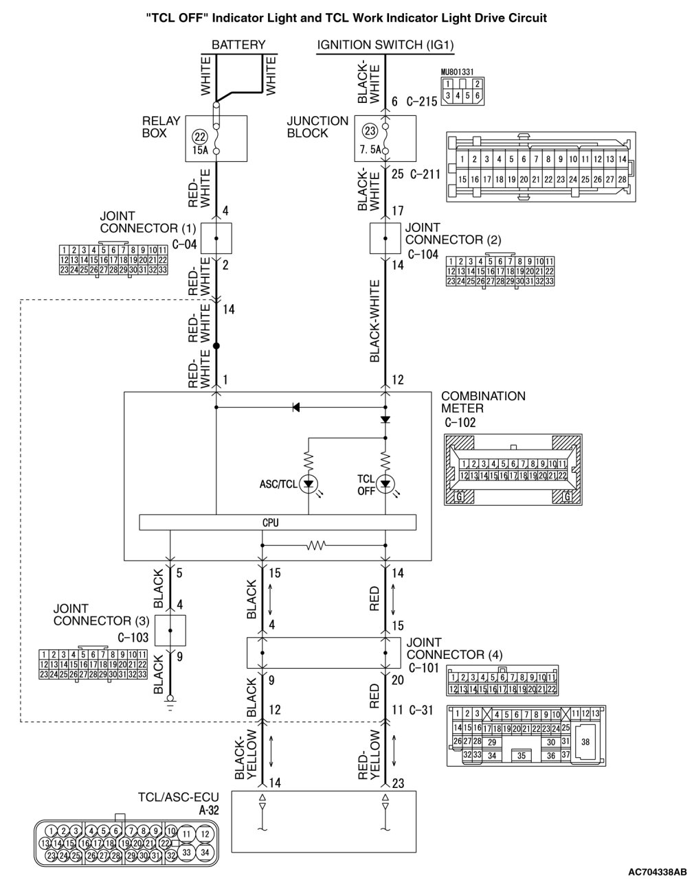
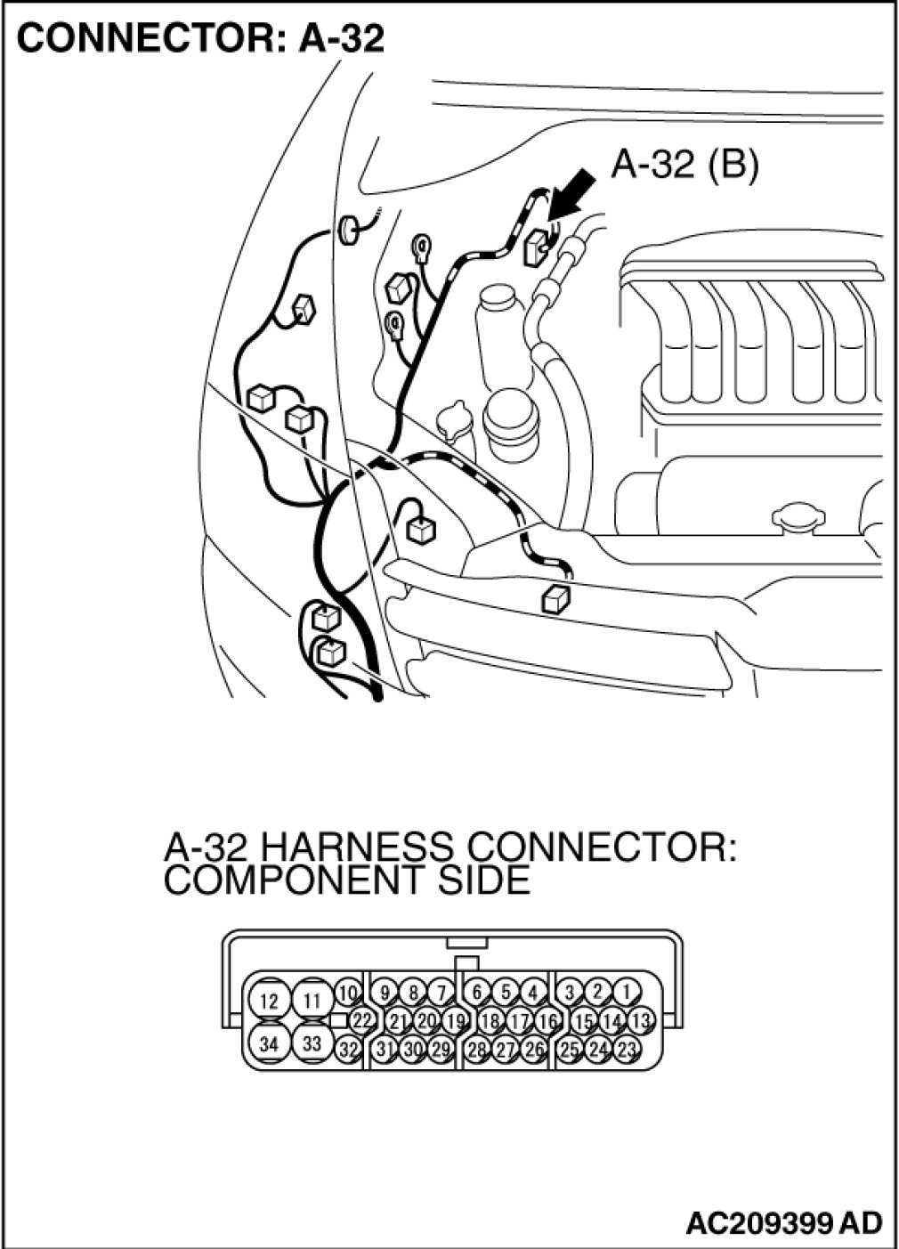
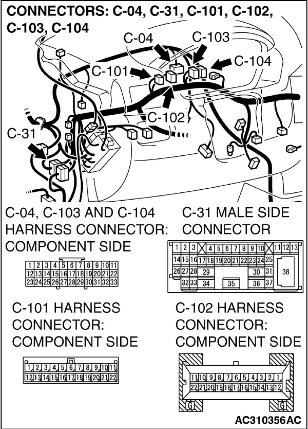
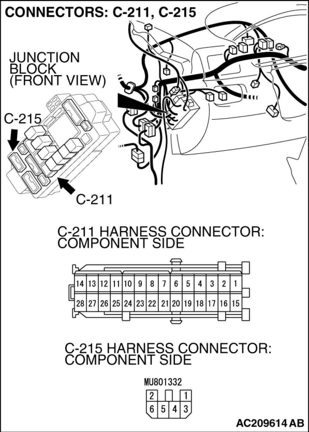
CIRCUIT OPERATION
- TCL/ASC-ECU send the illumination signal of "TCL OFF" indicator light and TCL work indicator light to the combination meter via the CAN communication.
- TCL/ASC-ECU operates the "TCL OFF" indicator light and the TCL work indicator light for three seconds after the ignition switch is turned "ON" position for bulb check.
COMMENT
This may be caused by faults in the CAN bus line, the combination meter or the TCL/ASC-ECU.
TROUBLESHOOTING HINTS
- Malfunction of the combination meter
- Damaged harness, connector
- Malfunction of the TCL/ASC-ECU
DIAGNOSIS
Required Special Tools:
- MB991958: Scan Tool (M.U.T.-III Sub Assembly)
- MB991824: V.C.I.
- MB991827: M.U.T.-III USB Cable
- MB991910: M.U.T.-III Main Harness A
STEP 1. Using scan tool MB991958, diagnose the CAN bus line.
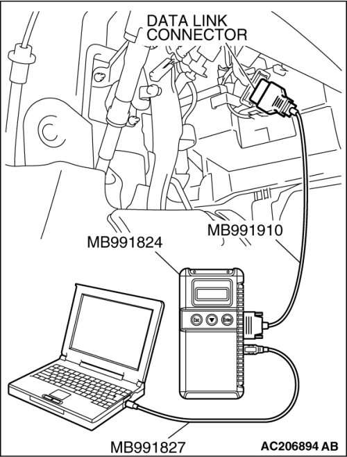
(1)
CAUTION:
To prevent damage to scan tool MB991958, always turn the ignition switch to the "LOCK" (OFF) position before connecting or disconnecting scan tool MB991958.
Connect scan tool MB991958 to the data link connector. (Refer to Reading and Clearing Diagnostic Trouble Codes).
(2)Turn the ignition switch to the "ON" position.
(3)Diagnose the CAN bus line. (Refer to Scan Tool Testing and Procedures).
(4)Turn the ignition switch to the "LOCK" (OFF) position.
(5)Disconnect scan tool MB991958.
Q. Is the check result satisfactory?
YES Go to Step 2
NO Repair the CAN bus lines. CAN Bus Diagnostics Chart). Then go to Step 4.
STEP 2. Using scan tool MB991958, read the diagnostic trouble code.
(1)
CAUTION:
To prevent damage to scan tool MB991958, always turn the ignition switch to the "LOCK" (OFF) position before connecting or disconnecting scan tool MB991958.
Connect scan tool MB991958 to the data link connector. (Refer to Reading and Clearing Diagnostic Trouble Codes).
(2)Turn the ignition switch to the "ON" position.
(3)Use scan tool MB991958 to read the TCL diagnostic trouble codes. (Refer to Reading and Clearing Diagnostic Trouble Codes).
(4)Turn the ignition switch to the "LOCK" (OFF) position.
(5)Disconnect scan tool MB991958.
Q. Is any DTC set?
YES Refer to Traction Control System (TCL), Diagnostic Trouble Code Chart. Then go to Step 4.
NO Go to Step 3.
STEP 3. Using scan tool MB991958, read the diagnostic trouble code.
(1)
CAUTION:
To prevent damage to scan tool MB991958, always turn the ignition switch to the "LOCK" (OFF) position before connecting or disconnecting scan tool MB991958.
Connect scan tool MB991958 to the data link connector. (Refer to Reading and Clearing Diagnostic Trouble Codes).
(2)Turn the ignition switch to the "ON" position.
(3)Check for Combination meter system diagnostic trouble code. Reading and Clearing Diagnostic Trouble Codes).
(4)Turn the ignition switch to the "LOCK" (OFF) position.
(5)Disconnect scan tool MB991958.
Q. Is DTC U1102 set?
YES Replace the hydraulic unit (integrated with TCL/ASC-ECU). Service and Repair). Then go to Step 4.
NO Replace the combination meter assembly. Combination Meter Assembly Removal and Installation). Then go to Step 4.
STEP 4. Retest the system
Q. Turn the ignition switch to the "ON" position. Do the "TCL OFF" indicator light and the TCL work indicator light illuminate for three seconds, and then go out after the engine starts?
YES The procedure is complete.
NO Return to Step 1.