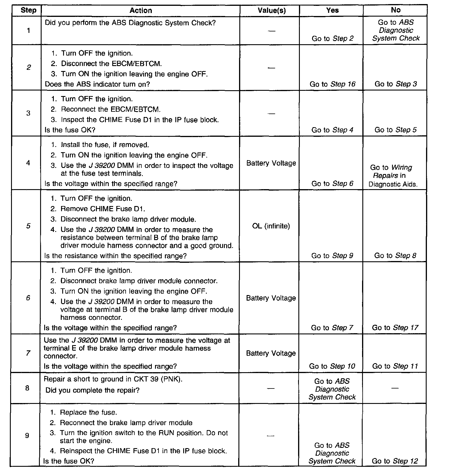
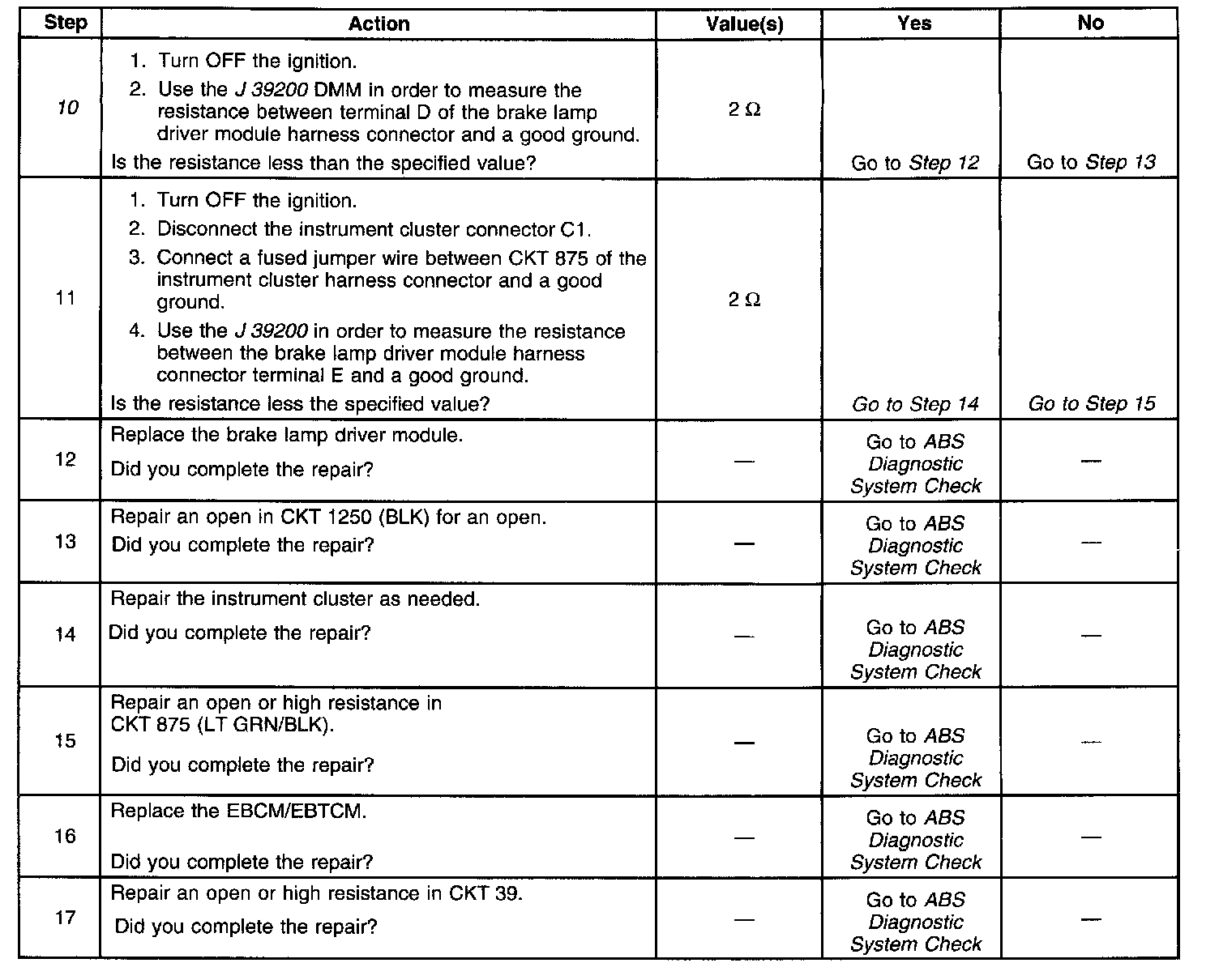
ABS Indicator Inoperative W/No DTC Set
Part 1 Of 2:
Part 2 Of 2:
CIRCUIT DESCRIPTION
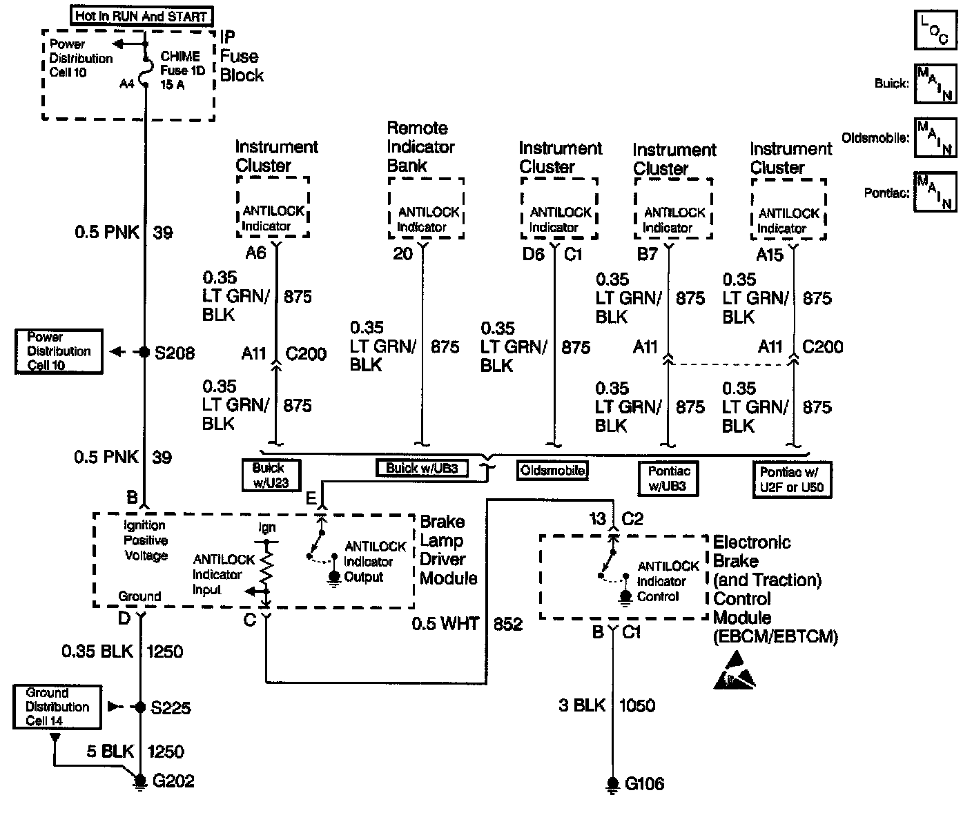
The EBCM/EBTCM controls the ABS indicator through the brake lamp driver module. The instrument cluster or remote indicator bank supplies voltage to the ABS indicator. The brake lamp driver module acts as an inverter. When the EBCM/EBTCM supplies a ground to the brake lamp driver module, the indicator remains OFF. When the EBCM/EBTCM removes ground from the brake lamp driver module, the brake lamp driver module supplies ground to the ABS indicator.
DIAGNOSTIC AIDS
^ It is very important that a thorough inspection of the wiring and connectors be performed. Failure to carefully and fully inspect wiring and connectors may result in misdiagnosis, causing part replacement with reappearance of the malfunction.
^ An intermittent malfunction can be caused by poor connections, broken insulation, or a wire that is broken inside the insulation.
^ If an intermittent malfunction exists, refer to Intermittents and Poor Connections Diagnosis.
TEST DESCRIPTION
The number(s) below refer to the step number(s) on the diagnostic table.
2. This step inspects if the EBCM/EBTCM is not capable of removing the ground for CKT 852 (WHT).
5. This step inspects for a short to ground in CKT 39 (PNK).
6. This step inspects for voltage at the brake lamp driver module.
7. This step inspects for voltage from instrument cluster.
10. This step inspects if the brake lamp driver module has a good ground.