Chart A-5 Fuel Pump Relay Circuit Diagnosis
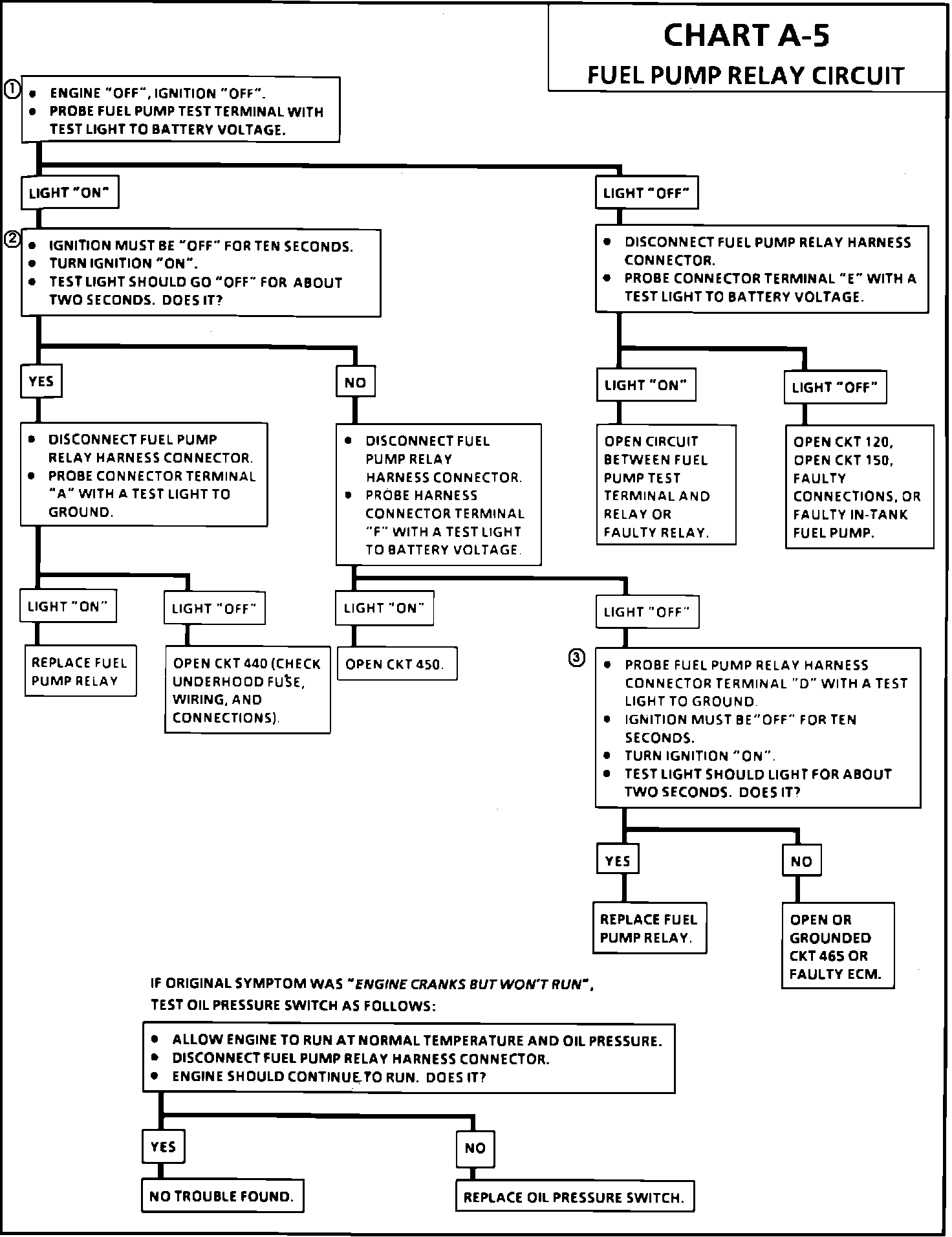
Chart A-5:
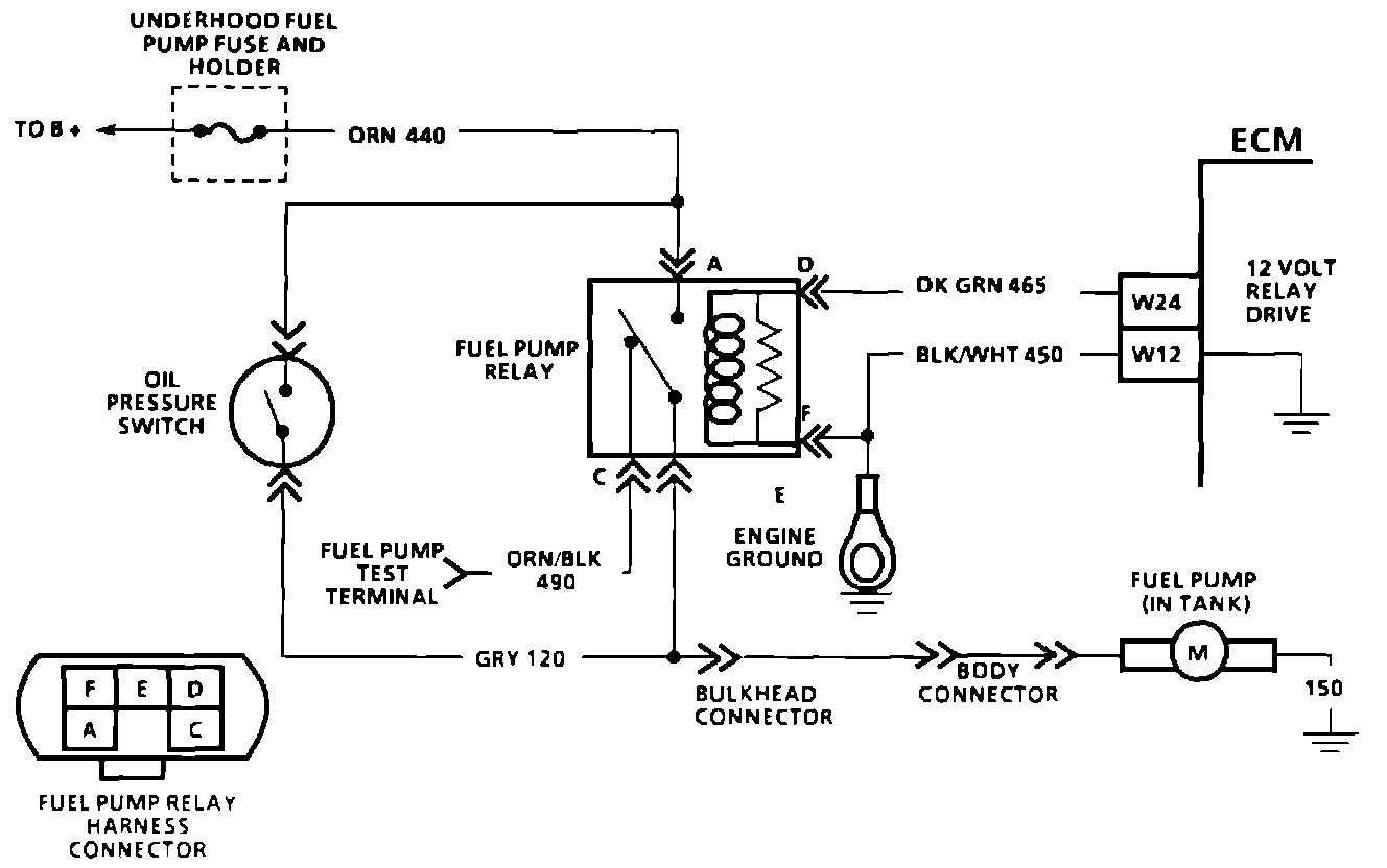
Wiring Diagram For Fuel Pump Relay:
CIRCUIT DESCRIPTION:
When the ignition switch is turned "ON," the ECM will energize the fuel pump relay and the in-tank fuel pump. It will remain "ON" as long as the engine is cranking or running, and the ECM is receiving ignition reference pulses. If there are no reference pulses, the ECM will shut "OFF" the fuel pump within 2 seconds after the ignition is "ON" or engine stops. Should the fuel pump relay or the 12.0 volts used to drive the relay fail, the fuel pump will be controlled through the oil pressure switch back-up circuit. When the engine is stopped, the pump can be turned "ON" by applying battery voltage to the test terminal. See COMPONENT LOCATIONS for fuel pump test connector.
TEST DESCRIPTION: The numbers below refer to circled numbers on the diagnostic chart.
1. This check determines if circuits 150 and 120 are OK.
2. If the ECM does not receive reference pulses within 2 seconds, it will turn "OFF" the relay.
3. This test will determine if the ECM is activating the relay.
DIAGNOSTIC AIDS:
1. This check determines if the oil pressure switch is faulty. Since it is in the back-up component, it must be checked without the fuel pump relay connected.
2. This check determines if the oil pressure switch is shorted internally.
NOTE: An inoperative fuel pump relay can result in an extended cranking time, particularly if the engine is cold or engine oil pressure is low. If the oil level is low, oil pressure will take a while to build-up in order to energize the fuel pump.
CAUTION: Not all SCAN testers are compatible with every system. A SCAN tool that produces faulty readings should NOT be used, and the problem should be reported to the tool manufacturer. Use of a faulty SCAN tool can result in improper diagnosis and unnecessary component replacement. Follow the proper instructions, located in the owners manual, for the specific SCAN tool being used.