Transmission
Transmission
=> [ 5th Gear, Installing ]
Special tools, testers and auxiliary items required
• Holding Plate (VW 309)
• Transmission Support (VW 353)
• Needle Bearing Drift (VW 295)
• Driving Sleeve (VW 244 B)
• Hot Air Blower (V.A.G 1416)
• Torque Wrench (5-50 Nm) (V.A.G 1331)
• M8 x 100 mm Bolt
• Bracket (30-211A)
• Driving Sleeve (32 -111)
• Thrust Piece (T10030/4)
• Tube 37 mm Dia. (VW 416 B)
• Puller (T10408)
• M7 x 35 Bolts with Washers
• Kukko Puller 65-160 mm (Kukko 18/1)
• Support Bridge (T10323)
• Wheel Bearing Assembly Set (3253/7)
• Thrust Pad Con. 8/65 (VW 433)
• Torque Wrench (40-200 Nm( (V.A.G 1332)
Removing
- Remove the clutch release lever, the release bearing and the guide sleeve. Refer to => [ Clutch Release Mechanism ] Service and Repair.
• Be careful not to damage the bearing for the input and output shafts when removing and installing 5th gear.
• When securing the transmission to the transmission support (VW 353), mount the following tools for support:
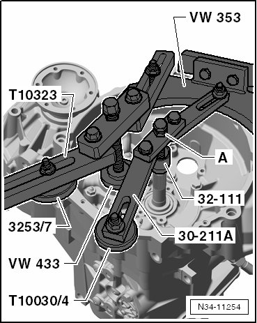
Under the Input Shaft:
• Bracket (30-211A)
• Driving sleeve (32 - 111)
• Thrust piece (T10030/4)
- Secure the bolt on the bracket (30-211A) with the nut - A -.
Under the Output Shaft Bracket:
• Support bridge (T10323)
• (3253/7) from the wheel bearing assembly set
• Thrust pad con. 8/65 (VW 433)
- Secure the transmission on the transmission support (VW 353).
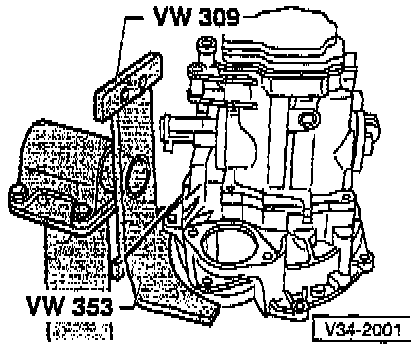
- Place the drip tray (V.A.G 1306) underneath.
- Open the oil filler plug and the oil drain plug.
- Drain the transmission fluid.
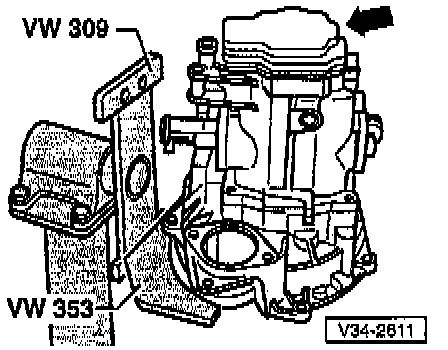
- Remove the transmission housing cover - arrow -.
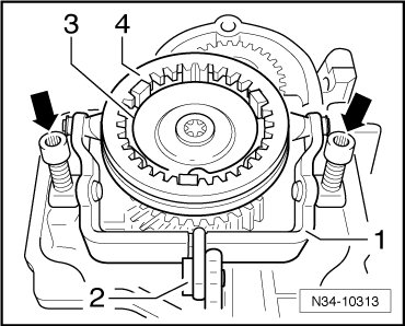
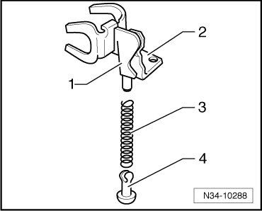
Remove the 5th gear selector fork as follows:
- Cover the openings with a cloth.
- Move the selector fork - 1 - into neutral.
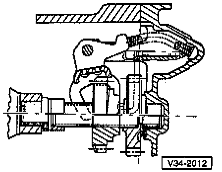
- Remove the bolt - 2 - for the 5th gear shift jaw.
- Remove both bolts - arrows - for the selector fork bases.
- Remove the selector fork bases.
- Remove the selector fork.
- It is not necessary to remove the spring - 3 - and the locking collar - 4 -.
- Engage 5th gear - arrow 1 - and 1st gear - arrows 2 and 3 - and then remove the bolts - A - for the synchronizing hub with operating sleeve and for the 5th gear.
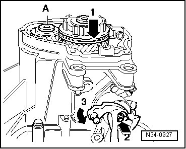
- The input and output shafts are blocked after engaging both gears, the synchronizer hub and the toothed gear cannot turn. Both bolts can be loosened now.
• Remove any locking compound residue still in the threaded holes using a thread tap if the shafts are not going to be replaced.
- Remove both bolts - arrows - for the reverse gear shaft support.
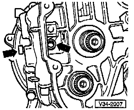
- Remove the 3rd bolt - arrow - for the reverse gear shaft support.
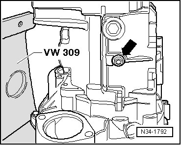
- Transmission on vehicles with a stop/start system: remove the transmission neutral position sensor (G701) - arrow -.
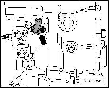
- Move the gear shift unit into neutral and remove the gear shift unit with the shift cover. Remove the bolts - arrows - and pull the gear shift nit out of the transmission housing.
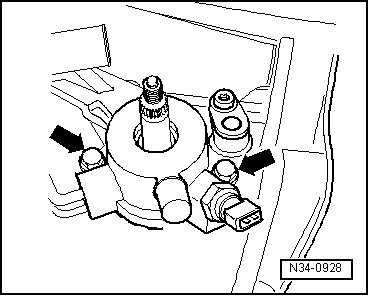
- Remove the sealing cap - A - and support pins - B - from the bottom of the transmission.
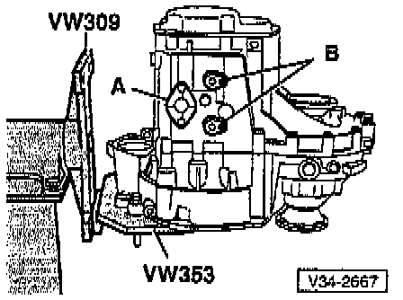
- Remove the support pins - A - from the top side of the transmission and remove the bolts - B - for the transmission housing to clutch housing in the area of the differential.
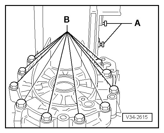
- Remove the bolts - A - that connect the clutch and transmission housing.
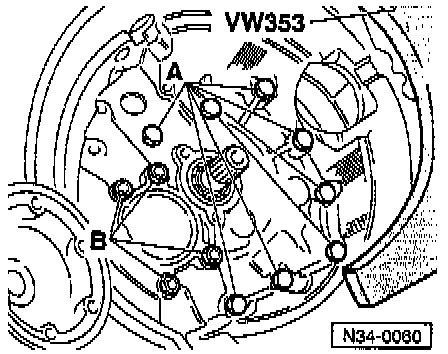
• Do not remove the nuts - B - for the bearing mount on the output shaft.
- Remove both flange shafts.
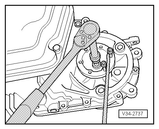
- Remove the flange shafts with the springs, thrust washers and tapered rings.
Remove the following components together with the transmission housing:
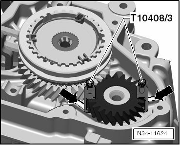
• 5th gear synchronizing hub with operating sleeve
• 5th gear
• Both straps (T10408/3) must be attached to the 5th gear.
• The straps (T10408/3) must be located above the 2 ribs on the housing, opposite each other - arrows -.
• There is a needle bearing under the 5th gear.
• Secure the straps (T10408/3) so that the needle bearing does not touch the 5th gear when removing the transmission housing.
Use puller (T10408) together with the following special tools:
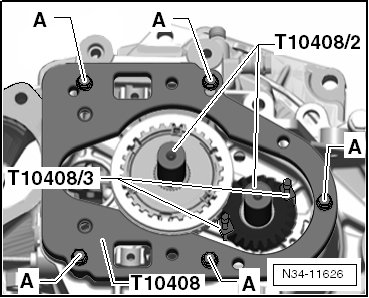
• Pressure pieces (T10408/2)
• Straps (T10408/3)
• Kukko Puller 65-160 mm (18/1)
- Secure the plate (T10408) in the threaded holes in the transmission housing cover.
A M7 x 35 bolts with washers
Tightening specification: 18 Nm
- Place the Pressure pieces (T10408/2) on the shafts.
- Install the Kukko puller 65-160 mm (18/1) - A -.
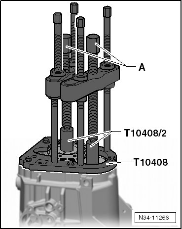
- Remove the 5th gear synchronizing hub with operating sleeve, the 5th gear and the transmission housing by tightening the spindles - A - - (approximately 1/2 turn).
- Warm the 5th gear slightly using the hot air blower (V.A.G 1416).
- Remove the selector forks - A - with the rails.
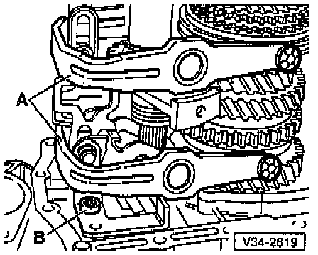
- Remove the shift mechanism/reverse gear - B -.
- Remove the nuts - B - from the bearing mount/output shaft.
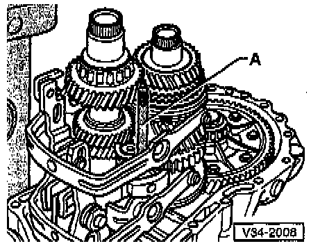
- Remove the reverse gear - A -, the input shaft - B - and the output shaft - C -, one after the other, from the clutch housing.
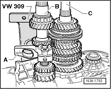
- Remove the differential.
Assembly
- Install the differential.
- Always replace the seals - arrows - for the bearing mount/output shaft.
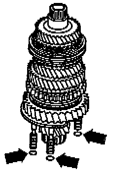
• The illustration only shows 3 of the 4 seals.
- Insert the input shaft - 1 - and output shaft - 2 - together.
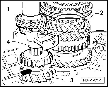
- Tighten the output shaft bearing mount nuts, see - item 11 - in => [ Input Shaft, Output Shafts, Differential and Shift Forks ] Transmission Component Overviews to specification.
- Place the reverse gear drive gear - 3 - on needle bearing in clutch housing.
The shoulder - arrow - faces away from the clutch housing.
- Make sure the reverse shaft - 4 - is complete, refer to => [ Reverse Shaft ] Reverse Shaft ; do not mount the support on the reverse shaft.
- Install the reverse shaft into the clutch housing.
- Clean all threaded holes in the reverse shaft supports of locking compound; cleaning can be done with a thread tap.
- Mount the reverse gear shaft support.
- Install the reverse gear selector fork - 1 - with the support for the reverse gear shaft - 2 -, the spring - 3 - and the sliding piece - 4 -.
Reverse gear location
- Install the shift mechanism/reverse gear - A -.
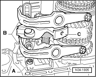
- Install the selector forks - B - together with the rails.
Reverse gear supports - C - are located in front of the selector rails.
- Install M 8 x 100 mm studs - A - into the reverse gear shaft support so that the shaft is aligned after fitting the transmission housing.
- Align the selector rails.
• The shift segments must be installed in the grooves on the locking collars.
- Apply sealing paste (AMV 188 200 03) evenly onto the sealing surface of the clutch housing.
- Install the transmission housing.
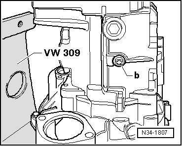
Install the bolts for the reverse gear shaft support - arrow - as follows:
- Install the bolt - a -.
- Remove the stud bolt - A - (⇒ upper illustration).
- Install the bolt - c -.
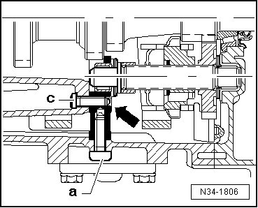
Tightening sequence:
- Tighten the bolt - a - to 30 Nm.
- Tighten the bolt - b - (⇒ lower illustration) to 25 Nm.
- Tighten the bolt - c - to 25 Nm.
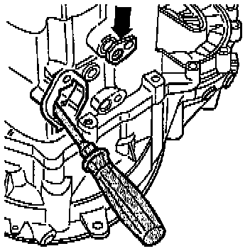
- Install the support pin - arrow - for the selector forks. To do this align the shift mechanism using a screwdriver, so that the relevant support pin can be installed.
- Apply sealing paste (AMV 188 200 03) evenly onto the sealing surface of the sealing cover.
- Install the gear shift unit.
Install the gearshift shaft cover as follows:
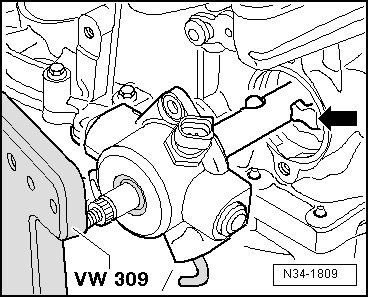
- Move the gear shift unit into the neutral position.
- Apply sealing paste (AMV 188 200 03) evenly onto the sealing surface of the cover.
- Move the gear unit into neutral.
- Position the selector shaft so that selector finger - arrow - is inserted into the selector rails.
- Tighten the gear shift unit cover bolts to specification, see - item 17 - in => [ Transmission Housing and Shift Mechanism ] Transmission Component Overviews.
- Transmission on vehicles with a stop/start system: install the transmission neutral position sensor - arrow - and tighten the bolt, see - item 11 - in => [ Transmission Housing and Shift Mechanism ] Transmission Component Overviews to specification.
- Install both flange shafts with springs, thrust washers and tapered rings. Refer to => [ Transmission Component Overviews ] Transmission Component Overviews.
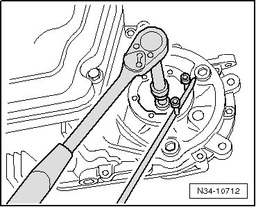
5th Gear, Installing
• Make sure the bracket (30-211A) and the support bridge (T10323) are installed.
- Secure the bolt on the bracket (30-211A) with the nut - A -.
Installed Position, 5th Gear
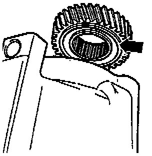
The groove all the way around - arrow - faces the transmission housing.
- Install the 5th gear.
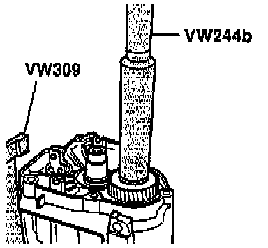
Checking 5th Gear Synchronizer Ring
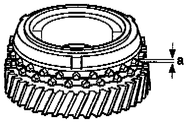
- Before reinstalling the gear and synchronizer ring for 5th gear, press the synchronizer ring onto the taper of the gear and measure the gap dimension - a - using a feeler gauge.

- Install the 5th gear with needle bearing.
- Place the 5th gear synchronizer ring onto the gear.
- If disassembled, assemble the 5th gear synchronizing hub with operating sleeve. Refer to => [ Assembling the 5th Gear Locking Collar/Synchronizer
Hub ] Input Shaft.
Installed Position of 5th Gear Synchronizer Hub/Locking Collar
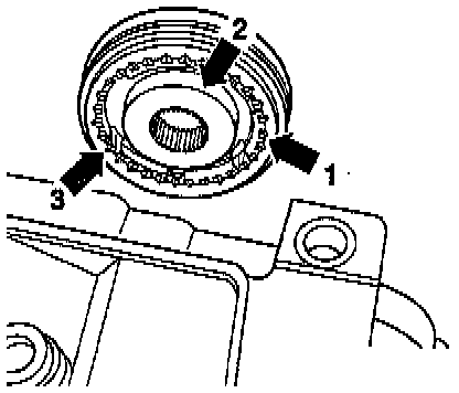
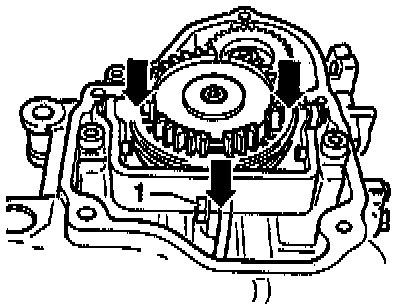
The pointed teeth on the locking collar - arrow 1 - and the high collar on the synchronizer hub - arrow 2 - face the transmission housing.
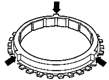
The notches - arrow 3 - on the synchronizer hub must line up with the cast locking pieces on the synchronizer ring (lower).
5th Gear Synchronizer Ring with Cast Locking Pieces
- Cover all openings with a cloth to prevent foreign objects from getting into the transmission.
- Install the 5th gear synchronizing hub with operating sleeve.
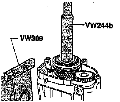
• Make sure there is enough clearance when installing the synchronizing hub.
- Loosen the input shaft support.
Wear safety gloves.
- Clean the synchronizing hub and 5th gear threaded holes of locking compound residue with a thread tap.
Otherwise, there is the danger that the bolts could shear off.
- Install the synchronizing hub and 5th gear bolts.
Installed Position of the Concave Washers for the 5th Gear Synchronizing Hub and Gear Bolts
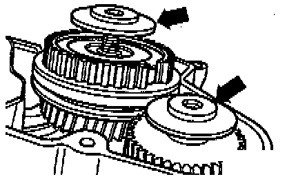
The outer diameter - arrows - faces 5th gear.
- Tighten the bolts for the synchronizing hub and 5th gear to specification. Refer to => [ Transmission Housing and 5th Gear Cover ] Transmission Component Overviews.
- Engage 5th gear - arrow 1 - and 1st gear - arrows 2 and 3 - and then tighten the bolts - A - for the synchronizing hub with operating sleeve and the 5th gear to specification. See - item 4 - in => [ Transmission Housing and 5th Gear Cover ] Transmission Component Overviews.
- The input and output shafts are blocked after engaging both gears, the synchronizing hub and the toothed gear cannot turn. Both bolts can be tightened now.
- Install the 5th gear selector fork.
Adjusting 5th Gear
- Engage 5th gear. Loosen the bolt - 1 -. Press the locking collar and selector fork in the direction of the arrow, then tighten the bolt - 1 - to 25 Nm.
• Check measurement: it must not be possible to slide a 0.2 mm feeler gauge between the locking collar and drive gear. Repeat the adjusting procedure if necessary.
- Remove 5th gear. The locking collar must be in the neutral position. The synchronizer ring must move freely.
- Move the shift lever (selector lever) through all the gears.
- Install the transmission housing cover. Refer to => [ Transmission Housing and 5th Gear Cover ] Transmission Component Overviews.
- Install the guide sleeve for the release bearing. Refer to => [ Clutch Release Mechanism ] Service and Repair.
- Install the clutch release lever and release bearing. Refer to => [ Clutch Release Mechanism ] Service and Repair.
- Fill the transmission fluid, refer to one of the following:
• Rabbit, MY 2006-2009, refer to => [ Pay attention to the
following list for the subject - ] Transmission.
• Golf, from MY 2010, refer to => [ Pay attention to the
following list for the subject - ] Transmission.