Cooling System Components, Engine Side
Cooling System Components, Engine Side
Part 1
Part 2, refer to.
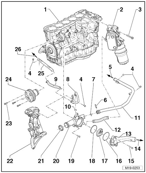
1 Cylinder Block
2 Oil Cooler
3 Bolt
• 25 Nm
4 Bolt/Nut
• 10 Nm
5 to Heater Core of Heater, Bottom
6 Retaining Clip
7 O-ring
• Replace
8 Front Coolant Pipe
9 Connecting Hose
10 O-ring
• Replace
11 Coolant Pipe
12 Connecting Hose
13 Connecting Piece
14 to Radiator, Bottom
15 Bolt
• 5 Nm
16 O-ring
• Replace
17 Coolant Thermostat
• Removing and installing, refer to => [ Coolant Thermostat ] Coolant Thermostat.
• Pay attention to the installed position: the valve must be at the top.
• Checking (coolant thermostat installed). Refer to the vehicle tester "Function and Component Selection".
• Checking (coolant thermostat removed):
Warm the thermostat in water.
Opens at: approximately 87 °C (188.6 °F) and stops at: approximately 102 °C (215.6 °F) opening travel: minimum 7 mm.
18 Seal
• Replace
19 Bolt
• 25 Nm
20 Coolant Thermostat Housing
21 Seal
• Replace
22 Accessory Bracket
23 Bolt
• 10 Nm
24 Coolant Pump
• With integrated silicone seal for sealing the cylinder block.
• Removing and installing, refer to => [ Coolant Pump ] Service and Repair.
25 Right Coolant Pipe
• Secured to the engine mount.
26 to Expansion Tank, Bottom
Part 2
Part 1, refer to.
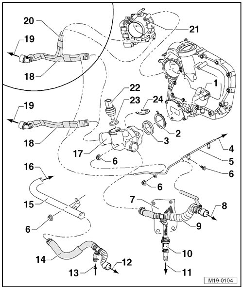
1 Coolant Connection
• Pressed in the cylinder head.
• Clean before installing the coolant distribution housing - item 17 -.
- If necessary, remove coolant deposits with a brass wire brush or with a fine sandpaper (minimum 100 grit).
• If the connection is worn, replace it using locking fluid (D 000600 A2).
2 Circlip
3 Seal
• Replace after removing the coolant distribution housing - item 17 -.
4 to Expansion Tank, Top
5 Rear Coolant Pipe
6 Bolt/Nut
• 10 Nm
7 Heat Shielding
8 to Heater Core, Top
9 Supply Hose
10 Bypass Thermostat
• Only for vehicles with a automatic transmission.
• Assembly overview, refer to.
• Checking, refer to.
11 to Automatic Transmission Fluid (ATF) Cooler
• Only for vehicles with a automatic transmission.
12 to Heater Core, Bottom
13 from Automatic Transmission Fluid (ATF) Cooler
• Only for vehicles with a automatic transmission.
14 Return Hose
15 Coolant Pipe
• Bolted to the coolant distribution housing - item 17 -.
16 to Coolant Distribution Housing
17 Coolant Distribution Housing
18 Supply Hose
19 to Top of Radiator
20 Coolant Hoses
• Only for the throttle valve control module heated by coolant.
21 Throttle Valve Control Module (J338)
22 Engine Coolant Temperature (ECT) Sensor (G62 )
23 O-ring
• Replace
24 Retaining Clip
Bypass Thermostat Assembly Overview
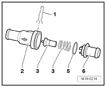
1 Spring bracket
2 Lower part of housing
Pay attention to the installed position: the arrow points to the ATF cooler
3 Operating element
4 Spring
5 O-ring
6 Upper part of housing
Bypass Thermostat Checking
- Remove operating element - 3 - and heat in a hot water bath.
Opens at: approximately 75 °C (167 °F)
Stops at: approximately 85 °C (185 °F)
Opening travel: approximately 5 mm