Shift Mechanism Overviews
Shift Mechanism Overviews
• Note the radio code on vehicles with a coded radio.
• Disconnect the ground cable from the battery when working on the shift mechanism inside the engine compartment.
• If the battery is to be reconnected, follow the work sequence after connecting the battery.
• When working on the shift mechanism in the engine compartment, remove the air filter housing, if it is located above the shift mechanism.
• The shift mechanism must be removed in order to replace the operating cables. Refer to => [ Shift Mechanism ] Shift Mechanism.
• Do not bend the operating cables.
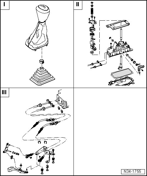
I - => [ Shift Knob and Boot ]
II - => [ Shift Lever and Housing, through 10.06 ]
II - => [ Shift Lever and Housing, from 11.06 ]
III - => [ Shift and Selector Cables ]
Shift Knob and Boot
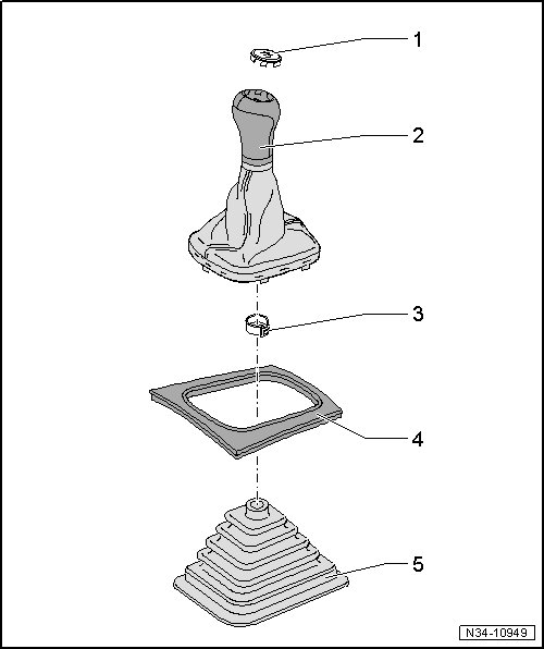
1 Emblem
• Can be carefully pried out of a plastic or leather shift knob.
2 Shift Knob
• With the boot
• The shift knob and boot cannot be separated from each other, always replace as an assembly.
• Removing and installing, refer to => [ Shift Knob, Boot and Noise Insulation ] Shift Knob, Boot and Noise Insulation.
3 Clamp
• For securing the shift knob to the shift lever.
• Attach to the shift knob using hose clamp pliers (V.A.G 1275).
• Always replace
4 Center Control Cover
• Combined in one piece with the upper center console section on some versions.
5 Noise Insulation
• Not on all vehicles.
• Arrow on the noise insulation points in direction of travel.
• Retaining tab spacing varies, therefore can only be arranged in one position.
Shift Lever and Housing, through 10.06
• Lubricate the bearing areas and the sliding surfaces.
• For the correct grease, refer to the Parts Catalog.
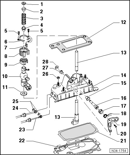
1 Lock Washer
• Removing and installing, refer to => [ Lock Washer, Removing and Installing ].
2 Bushing
3 Pressure Spring
4 Bushing
5 Bolt
• 5 Nm
6 Cover
7 Sound Insulation
8 Bearing Shell
9 Bearing Shell
10 Shift Lever Guide
11 Washer
12 Gasket
• Between the shift housing and the underbody.
• Self-adhesive
• Install to the shift housing.
13 Shift Lever
14 Shift Housing
15 Bushing
16 Pin
17 Bushing
18 Pressure Spring
• Installing, refer to => [ Pressure Spring, Installing ].
19 Selector Bracket
20 Bolt
• 5 Nm
21 Gasket
• Always replace
22 Base Plate
• Bend the tabs in order to remove/install.
• Always replace
23 Selector Cable
• To the selector bracket - 19 -.
• Removing and installing, refer to => [ Selector and Shift Cables, Removing
and Installing ].
24 Shift Cable
• Removing from/installing to the shift lever guide, refer to => [ Selector and Shift Cables, Removing
and Installing ].
25 Lock Washer
• Always replace
26 Nut
• M8 - 25 Nm
• M6 - 8 Nm
• Quantity: 4
27 Bushing
• Fits in one position only.
28 Lock Washer
• Always replace
Selector and Shift Cables, Removing and Installing
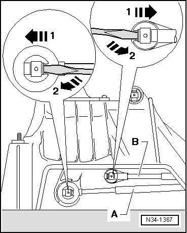
- Remove the lock washers from the shift cable - A - and the selector cable - B -.
Lift the tab with a screwdriver - arrow 1 - and remove the lock washer - arrow 2 -.
- Remove the shift cable - A - from the shift lever mount.
- Remove the selector cable - B - from the selector bracket.
Pressure Spring, Installing
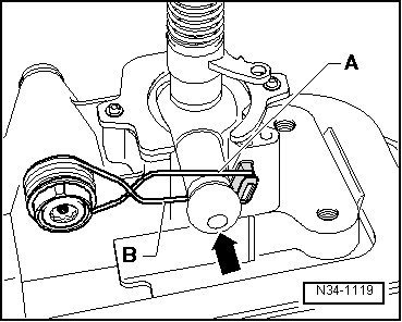
- Install the pressure spring so that the upper leg - A - contacts the upper part of the shift lever guide - arrow -.
- Pull the lower leg - B - downward so that it reached the bottom of the shift lever guide - arrow -.
Shift Lever and Housing, from 11.06
• Lubricate the bearing areas and the sliding surfaces.
• For the correct grease, refer to the Parts Catalog.
• Selector mechanism, disassembling and assembling. Refer to => [ Shift Mechanism, from 11.06 ] Shift Mechanism, from 11.06.
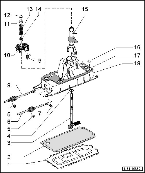
1 Base Plate
• Bend the tabs in order to remove/install.
• Always replace
2 Gasket
• Always replace
3 Shift Lever
• Can be removed and installed with the shift lever guide - 15 - installed.
4 Washer
• Slide onto the shift lever as far as the stop - arrow -.
5 Lock Washer
• Be careful not to damage the cables when removing them.
• Always replace
6 Selector Cable
• Pry off of the selector bracket.
• Press onto the selector bracket inside the shift mechanism.
• Installed position, refer to => [ Shift and Selector Cables, Installed Position ] Removal and Replacement.
7 Bushing
8 Shift Cable
• Pry off of the shift lever guide.
• Press onto the shift lever guide inside the shift mechanism.
• Installed position, refer to => [ Shift and Selector Cables, Installed Position ] Removal and Replacement.
9 Sound Insulation
10 Bearing Shell
• Will get damaged when being removed.
• Always replace
11 Bushing
12 Lock Washer
• Removing and installing, refer to => [ Lock Washer, Removing and Installing ].
13 Pressure Spring
14 Bushing
15 Shift Lever Guide
16 Nut
• M8 - 25 Nm
• M6 - 8 Nm
• Quantity: 4
17 Gasket
• Between the shift housing and the underbody.
• Self-adhesive
• Install to the shift housing.
18 Shift Housing
• With pressure spring and selector bracket.
• Pressure spring and selector bracket cannot be removed.
Lock Washer, Removing and Installing
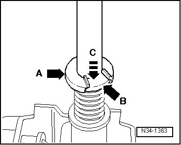
- Push the bushing - arrow B - all the way down in the - direction of arrow C - using a screwdriver and remove the lock washer - arrow A -.
• Do not tilt the bushing when pushing it down.
• The slot in the lever for the lock washer must be visible.
• Carefully release the tension on the pressure spring.
Shift and Selector Cables
• Lubricate the bearing areas and the sliding surfaces.
• For the correct grease, refer to the Parts Catalog.
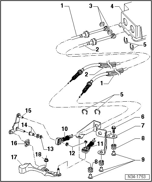
1 Shift Cable
• Attaches to the cable retainer - item 11 -.
• Installed position, refer to => [ Shift and Selector Cables, Installed Position ] Removal and Replacement.
• Attach to the selector cable with a cable tie, refer to => [ Cable Tie Installed Location ].
• From 11.06 changed fastener on shift lever inside shift mechanism, refer to - item 8 - in => [ Shift Lever and Housing, from 11.06 ].
2 Selector Cable
• Attaches to the cable retainer - item 11 -.
• Installed position, refer to => [ Shift and Selector Cables, Installed Position ] Removal and Replacement.
• Attach to the shift cable with a cable tie, refer to => [ Cable Tie Installed Location ].
• From 11.06 changed fastener on selector bracket inside shift mechanism, refer to - item 6 - in => [ Shift Lever and Housing, from 11.06 ].
3 Lock Washer
• Always replace
• Discontinued on shift mechanisms from 11.06. Refer to => [ Shift Lever and Housing, from 11.06 ].
4 Shift Housing
5 Lock Washer
• Always replace
• Be careful not to damage the cables when removing them.
6 Bolt
• 20 Nm
• Quantity: 3
• For the cable bracket to the transmission.
7 Cable Bracket
• Can be made of plastic or metal.
8 Grommet
• For the cable bracket to transmission.
9 Spacer Support
10 Cable Retainer
• Adjust the shift mechanism after installation. Refer to => [ Shift Mechanism, Adjusting ] Adjustments.
• For attaching the selector cable to the relay lever.
• Do not interchange, the cable locking mechanisms for the selector cable to the relay lever and for the shift cable to the transmission shift lever are different.
• Is secured with a lock washer - item 12 - with a metal relay lever.
• From 05.07 installed with the plastic relay lever. Refer to => [ Plastic Relay Lever ] Plastic Relay Lever.
• Removing from/installing to plastic relay lever. Refer to => [ Plastic Relay Lever ] Plastic Relay Lever.
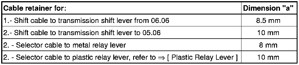
• Allocation, refer to => [ Cable Retainer Allocation ].
11 Cable Retainer
• Adjust shift mechanism after installation. Refer to => [ Shift Mechanism, Adjusting ] Adjustments.
• For attaching the shift cable to the transmission shift lever.
• Do not interchange, the cable locking mechanisms for the selector cable to the relay lever and for the shift cable to the transmission shift lever are different.
• Allocation, refer to => [ Cable Retainer Allocation ].
12 Lock Washer
• Always replace
• Not needed with the plastic relay lever.
13 Lock Washer
• Always replace
• Not needed with the plastic relay lever.
14 Bushing
• Not needed with the plastic relay lever.
15 Relay Lever
• Installed position, refer to => [ Selector Lever/Relay Lever, Installed
Position ].
• Adjust the shift mechanism after installation. Refer to => [ Shift Mechanism, Adjusting ] Adjustments.
• Can be made of plastic or metal.
• Install the metal relay lever into the bushings - item 14 - and secure it with lock washer - item 13 -.
• From 05.07 is a plastic relay lever.
• Plastic relay lever, removing and installing with cable retainer. Refer to => [ Plastic Relay Lever ] Plastic Relay Lever.
• The bushings and lock washers are not needed with the plastic relay lever.
16 Sliding Shoe
17 Shift Lever
• Installing, refer to => [ Transmission Shift Lever, Installing ].
• Installed position, refer to => [ Selector Lever/Relay Lever, Installed
Position ].
• Adjust the shift mechanism after installation. Refer to => [ Shift Mechanism, Adjusting ] Adjustments.
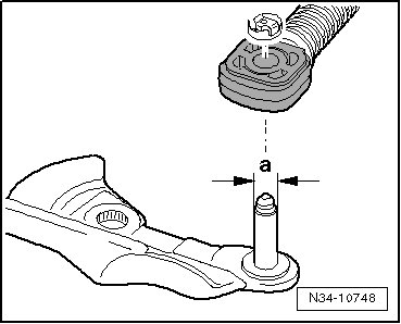
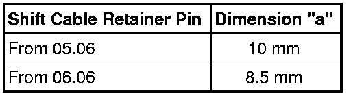
• As of 06.06 a smaller pin diameter for the cable retainer. Refer to => [ As of 02.06, Smaller Pin Diameter for
the Shift Cable Retainer ].
18 Self-Locking Nut
• 23 Nm
• Always replace
Cable Retainer Allocation
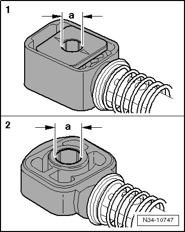
These holes have different diameters.
As of 02.06, Smaller Pin Diameter for the Shift Cable Retainer
Transmission Shift Lever, Installing
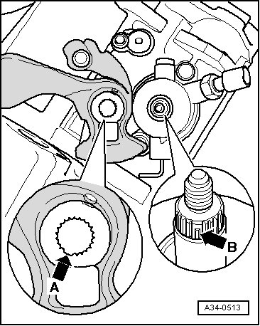
- When positioning the shift lever, make sure the gap - arrow A - is placed over the missing selector shaft teeth - arrow B -.
Selector Lever/Relay Lever, Installed Position
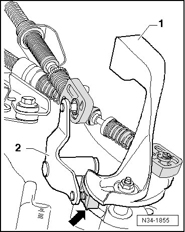
1 Shift lever
2 The relay lever fits into the sliding rail on the transmission shift lever via the sliding shoe - arrow -.
Cable Tie Installed Location
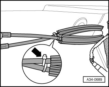
- Wrap the cable tie - arrow - in a crossover pattern around the cables and attach it as illustrated.