Heating and A/C Unit
Heating and A/C Unit
Special tools, testers and auxiliary items required
• A/C service station (VAS 6007A)
• drip tray for shop crane (VAS 6208)
• Hose clamps up to dia. 40 mm (VAS 3093)
• Compressed air gun, commercially available
Removing
• To improve accessibility, additional components e.g. engine cover must be removed (depending on engine version).
- Extract refrigerant e.g. using A/C service station (VAS 6007A), only then open the refrigerant circuit. Observe notes => [ Refrigerant Circuit ] Refrigerant Circuit.
- Remove the instrument panel.
- Remove rear channels for right and left footwells. Refer to => [ Rear Channel Footwell Duct ] Removal and Replacement.
- Place drip tray for shop crane (VAS 6208) under the engine.
Only for vehicles with shielding plate in front of expansion valve
- Remove the nut - 1 - (4.5 Nm) and the screw - 4 - (2.5 Nm).
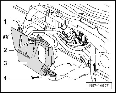
- Loosen the clip - 2 - and remove the shielding plate - 3 -.
All vehicles
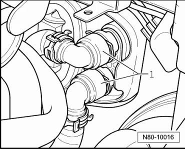
- Mark the coolant hoses - 1 - to prevent interchanging them.
CAUTION!
Contact with hot engine coolant can cause severe scalding.
Coolant temperature can be above 100 ? with a warm engine. The cooling system is under pressure.
If necessary, reduce pressure and temperature before repairs.
- Clamp off coolant hoses - 1 - using hose clamps up to dia. 40 mm (VAS 3093) and disconnect coolant hoses to heater core.
- Connect a section of hose - A - onto upper connection.
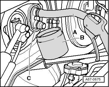
- Hold a container - B - under the lower connection - C -.
- Using a compressed air gun, carefully blow residual coolant out of heater core at heater core connection.
CAUTION!
There is a danger of ice-up.
Refrigerant may leak out if refrigerant circuit is not discharged.
Refrigerant must be extracted before opening refrigerant circuit.
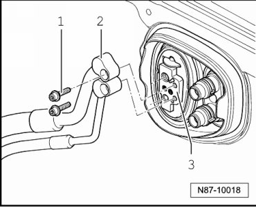
- Remove the refrigerant line - 2 - screws (10 ± 1 Nm), - 1 - from the engine compartment.
- Disconnect refrigerant lines from expansion valve - 3 -.
• Seal open pipe connections.
• To seal off all open connections on expansion valve, sealing caps from a replacement expansion valve can be used (preventing dirt and moisture from entering the system).
- Cover floor carpet in vehicle interior with leak-proof foil and absorbent paper.
• Take note during removal of the length and assignment of bolts for re-installation
1 Screw
• 4 Nm
2 Screws
• Quantity: 2
• 4 Nm
3 Cable bracket
4 Heating and A/C unit
Removing
- Disconnect condensation water hose from heating and A/C unit. Refer to => [ Condensation Water Drain Hose, Checking ] Testing and Inspection.
- Disconnect the connectors form the heating and A/C unit.
• All cable ties opened or cut during removal must be reinstalled at the same locations during installation.
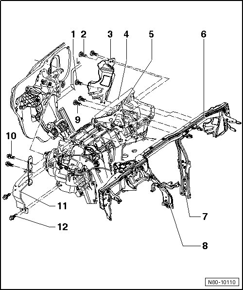
- Remove bolts - 9 - from bracket - 5 -.
- Remove the supports - 7 - and - 8 -.
- Remove bolts - 10 - and - 12 - and remove bracket - 11 -.
- Remove the screws - 1 - and - 2 - from the cable bracket - 3 -.
• To be able to reach the bolt - 1 -, heating and A/C unit on driver side must be pulled out slightly from facing wall.
• When removing heating and A/C unit, make sure the two coolant pipes of the heater core do not get caught and bent or damaged on plenum chamber or noise insulation pan.
• Also pay attention to wiring harness, individual wiring connections may get damaged when pulling too forcefully on wiring harness.
- Remove heating and A/C unit.
Installing
Installation is carried out in the reverse order. When doing this note the following:
• The assistance of a second technician is necessary to install the heating and A/C unit.
- When inserting heating and A/C unit, have the second technician guide both coolant pipes to heater core through the seal (from engine compartment)=> [ Seal for heating and A/C unit / engine compartment ].
- Fill with coolant.
5 Bracket
6 Assembly carrier
7 Right support
8 Left support
9 Screws
• 9 ± 1.3 Nm
10 Screws
• Quantity: 2
• 9 ± 1.3 Nm
11 Bracket
12 Screws
• Quantity: 2
• 9 ± 1.3 Nm
Seal for heating and A/C unit / engine compartment
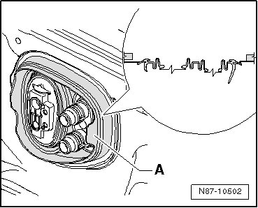
• Note installation position of seal - A - during assembly.