Intake Manifold Overview
Intake Manifold Overview
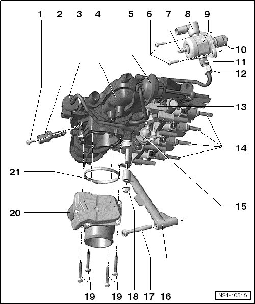
1 Bolt
• 5 Nm
2 Intake Air Temperature Sensor (G42)
3 EVAP Canister Purge Regulator Valve 1 (N80)
• With a check valve/restrictor as one unit.
• To remove and install, remove the intake manifold.
4 Intake Manifold
• Removing and installing, refer to => [ Intake Manifold with Fuel Rail ] Intake Manifold with Fuel Rail.
• Bolt tightening specification, see - item 15 - in the => [ Fuel Rail and Injector Overview ] Fuel Rail and Injector Overview.
5 Vacuum Diaphragm for the Channel Separating Plate
6 Bolt
• M6 threads = 8 Nm + an additional 90° (1/4) turn.
• M8 threads = 20 Nm.
• Always replace.
7 Fuel Line Connection
• From the fuel tank.
8 Fuel Pressure Regulator Valve (N276)
9 High Pressure Pump
• With the fuel pressure regulator valve.
• Make sure dirt does not enter the fuel system when installing the high pressure pump.
• The fuel system must be without pressure to install the high pressure pump, releasing the high side fuel pressure. Refer to => [ High Side Fuel Pressure, Releasing ] Service and Repair.
• Install the fuel line to the fuel rail free of tension.
• High pressure pump overview. Refer to => [ High Pressure Pump Overview ] High Pressure Pump Overview.
10 Cam Follower
• Remains inserted in the cylinder head after removing the high pressure pump, removable.
11 High Pressure Fuel Line Connection
• Tightening specification, refer to => [ High Pressure Pump Overview ] High Pressure Pump Overview.
12 Fuel Supply Line to High Pressure Fuel Pump
• 18 Nm
• Do not install the fuel line under tension.
13 Intake Manifold Runner Control Valve (N316)
14 Fuel Injector
• Replace the O-rings.
• Note the correct installed position.
• Removing and installing, refer to => [ Fuel Injectors ] Fuel Injectors.
15 Check Valve/Restrictor
• Allocations for differing versions, refer to the Parts Catalog.
• With the EVAP canister purge regulator valve 1 as one unit.
16 Intake Manifold Support
17 Bolt
• 23 Nm
18 Nut
• 10 Nm
19 Bolt
• Quantity: 4
• 5 Nm
20 Throttle Valve Control Module (J338)
• With the EPC throttle drive, the EPC throttle drive angle sensor 1 and the EPC throttle drive angle sensor 2.
• After replacing the throttle valve control module, it must be readapted to the Engine Control Module (ECM). Refer to "Guided Functions" in the vehicle diagnostic tester.
• Removing and installing, refer to => [ Throttle Valve Control Module J338 ] Removal and Replacement.
• Cleaning, refer to => [ Throttle Valve Control Module, Cleaning ] Procedures.
21 Seal
• Always replace.
• The rim of the seal must fit into the groove provided for it inside the intake manifold.