Lower Timing Chain Cover
Lower Timing Chain Cover
Special tools, testers and auxiliary items required
• Engine Support Bridge (10-222 A)
• Shackle (10-222 A/12)
• Locking Pin (T10060 A)
• Counter Hold Tool (T10355)
• Thrust Piece (T10368)
• Bits (T10099)
• Bracket for Engine (10-222 A/1) (for the Passat only)
• Engine Support Feet (10-222 A/8) (for the CC only)
Removing
- Remove the noise insulation. Refer to one of the following:
Eos and Passat
CC
- Remove the front part of the right wheel housing liner..
- Drain the engine oil.

- Remove the bolts - arrows -.
- Lift the clamps - 1 and 2 - and remove the charge air pipe.
Risk of destroying due to a reversed running direction of a used ribbed belt.
• Before removing the ribbed belt, mark the running direction with chalk or a felt-tip pen for reinstallation later.
- Remove the right charge air hose - arrows -.

- To release the tension on the ribbed belt, turn the tensioner in the - direction of the arrow - from underneath.

- Secure the tensioner using the locking pin (T10060 A).
- Remove the ribbed belt from the vibration damper.
- Rotate the vibration damper using the counter hold tool (T10355) into the TDC position - arrow -.

• The notch on the vibration damper must line up with the arrow mark on the lower timing chain cover.
Danger of causing damage to the engine.
• In order not to change the valve timing, the crankshaft must not be moved out of the TDC position when the vibration damper bolt is removed.
- Remove the vibration damper bolt using the counter hold tool (T10355).
- Remove the vibration damper.
To avoid damaging the splines, only use thrust piece (T10368) to install the vibration damper bolt.
- Install the vibration damper bolt and the thrust piece (T10368).

- Install the engine support bridge (10-222 A) using the following special tools:
Passat

• Bracket for engine (10-222 A/1)
• Bracket with spindle and hook (10-222 A/10)
• Shackle (10-222 A/12)
CC

• Engine support feet (10-222 A/8)
• Bracket with spindle and hook (10-222 A/10)
• Shackle (10-222 A/12)
• Do not place the engine support feet (10-222 A/8) on the fender panels. They will be damaged.
• The shackle (10-222 A/12) is needed to make sure the engine is lifted in the installed position and not tilted.
Continuation for All
- Tension the engine with the spindle.
- Remove the engine mount to engine mount bracket bolts - arrows -.

- Remove the engine mount. Refer to => [ Engine/Transmission Mount Overview ] Service and Repair.
- Lift the engine approximately 50 mm and loosen the upper bolt for the engine mount bracket.
- Now, lower the engine approximately 100 mm.
- Free up the wiring harness - arrow -.

- Remove the bolt - 1 - and remove the ribbed belt tensioner from the accessory bracket.
- Loosen the lower bolts for the engine mount bracket using the bits (T10099).
- Remove the engine mount bracket and the bolts.
- Remove the bolts - arrows - and remove the oil dipstick guide tube from the upper timing chain cover.

- Remove the wastegate bypass regulator valve bolts - arrows - and valve from the turbocharger.

- Remove the connection bolts - 1 - and connection from the turbocharger.
- Remove the lower timing chain cover bolts - 1 through 15 -.
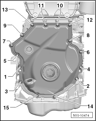
• There may be 8 bolts installed, depending on the version.
The lower timing chain cover could be damaged. To avoid deformation, do not hold between the bolting points.
- Pry the lower timing chain cover off, when doing this, begin at - 1 and 2 -.

Installing
• For the correct tightening specifications, refer to => [ Timing Chain Cover Overview ] Timing Chain Cover Overview.
• Sealant, use silicone sealant (D 174 003 A2).
• If the cover was bent while it was being removed, it must be replaced.
• Note the expiration date of the silicone sealant.
• The cover must be installed within 5 minutes after application of the silicone sealant.
• Replace the bolts which have been tightened an additional torque angle
• Replace the sealing rings, seals and self-locking nuts.
• Risk of contaminating the lubricating system. Cover open parts of the engine.
• Wear protective eye wear.
- Remove any sealant residue on the cylinder block using a flat blade scraper.
- Seal off both side of the seal with tape to prevent contamination.
- Use a rotating plastic brush to remove any remaining sealing on the cover.

- Clean the sealing surfaces, they must be free of oil and grease.
Checking the Cover for Distortion
- Install the cover using the old bolts and tighten them to 8 Nm.
- Check between the cover and housing using a feeler gauge, the gap must not exceed 0.2 mm.
• If the gap exceeds 0.2 mm, replace the cover.
• It is not possible to measure between the cover the upper oil pan, however check the sealing surface for evenness.
Installing the Cover
- Make sure both alignment sleeves - arrows - for centering the cover are present.

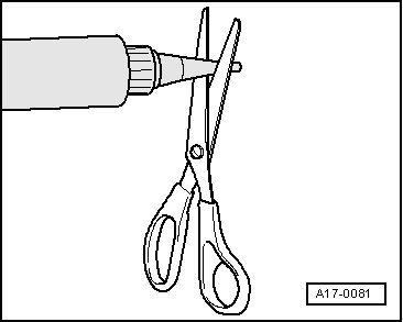
- Cut the sealant tube nozzle at the front mark (nozzle diameter: approximately 0.12 in).
Cover with 15 Bolts

- Apply the silicone sealant (D 174 003 A2) on the clean sealing surface - arrow 1 - and on the edges - arrows 2 - of the new cover as shown in the illustration.
• Thickness of sealant bead: 2 to 3 mm
Cover with 8 Bolts

- Apply the silicone sealant (D 174 003 A2) on the clean sealing surface - arrow 1 - and on the edges - arrows 2 - of the new cover as shown in the illustration.
• Thickness of sealant bead: 2 to 3 mm
• The cover must be installed within 5 minutes after application of the silicone sealant.
• The sealant bead may not be thicker than specified, otherwise the excess sealant could enter the oil pan and clog the oil suction pipe.
- Immediately install the cover and tighten the bolts:
• Cover with 15 bolts, refer to => [ Lower Timing Chain Cover Bolt Tightening Sequence, with 15 Bolts ] Timing Chain Cover Overview.
• Cover with 8 bolts, refer to => [ Lower Timing Chain Cover Bolt Tightening Sequence, with 8 Bolts ] Timing Chain Cover Overview.
• After installing the cover, allow the sealant to dry for approximately 30 minutes. Only after then may the engine oil be added.
- Fill the engine oil.
- Check the oil level.
Further installation is in the reverse order of removal.