Procedures
Crankshaft, Locking
Special tools, testers and auxiliary items required
• Torque Wrench (5-50 Nm) (V.A.G 1331)
• Crankshaft Adapter (T03003)
• Locking Pin (T40069)
Procedure
- Remove the noise insulation.
- Remove the front section of the right wheel housing liner..
- Install the crankshaft adapter (T03003) onto the bolts of the vibration damper.
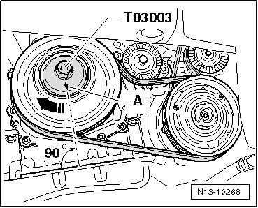
The crankshaft adapter (T03003) can only be installed correctly in one position.
- Rotate the crankshaft in engine rotation direction until the arrow - A - on the crankshaft adapter (T03003) faces downward vertically in comparison to the engine axis.
This position corresponds approximately to the Top Dead Center (TDC) position of the crankshaft at cylinder 5.
- Remove the locking bolt - 1 - from the rear of the cylinder block.
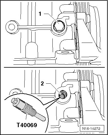
- Look through the threaded hole and check whether the bore - 2 - in the crankshaft aligns with the threaded hole.
Use a mirror to do so, if necessary.
- Rotate the crankshaft slightly if necessary.
- If the bore and the hole align, install the locking pin (T40069) completely into the threaded hole and tighten it to 10 Nm.
• With the engine removed, the TDC mark can also be seen on the vibration damper and sealing flange. The notches - A and B - must align.
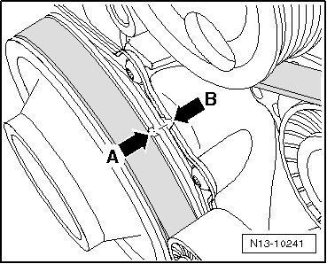
- Check whether the crankshaft can be rotated.
After Disassembly and Assembly Work
- Remove the locking pin (T40069) and install the locking bolt - 1 -.
The rest of the installation follows the reverse of the removal procedure.
Tightening Specifications
