Engine Overview, Rear
Engine Overview, Rear
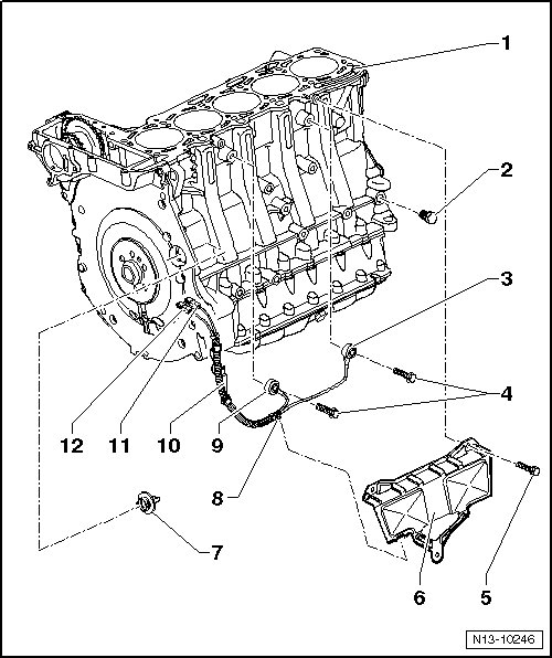
1 Cylinder Block
2 Locking Bolt
• 30 Nm
• With a rolled seal.
• The bore in the cylinder block is used for locking the crankshaft using the locking pin (T40069).
3 Knock Sensor 1 (G61)
• Note the installed position: The wire connection points downward vertically.
4 Bolt
• 20 Nm
• Tightening specification affects the function of the knock sensor.
5 Bolt
• 10 Nm
6 Cover
7 Plug
8 Wire Clip
• Clipped to the cover plate.
9 Knock Sensor 2 (G66)
• Note the installed position: The wire connection points 45° toward the right on the outside.
10 Wire Bracket
• Bolted to the Secondary Air Injection (AIR) valve.
11 Connector
• Green for knock sensor 1.
• Installed position, refer to => [ Installed Position of the Knock Sensor Harness Connectors ].
• Contacts are gold plated.
12 Connector
• Gray for knock sensor 2.
• Installed position, refer to => [ Installed Position of the Knock Sensor Harness Connectors ].
• Contacts are gold plated.
Installed Position of the Knock Sensor Harness Connectors
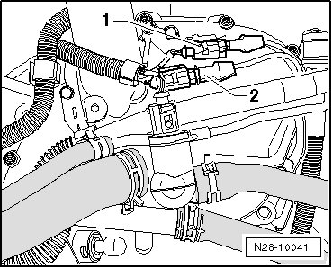
1. Green for knock sensor 1
2. Gray for knock sensor 2