Cooling System
Coolant Hose Connection Diagram
• When the engine is warm the cooling system is under pressure. If necessary release pressure before beginning any repair work.
• Hoses are secured with spring type clamps. In cases of repair only use spring type clamps.
• Hose clip pliers (VAS 6340) or (VAS 6362) are recommended for installing spring clamps.
• While installing, route coolant hoses free of tension and without them coming into contact with other components.
• The arrows on coolant pipes and coolant hoses must line up across from each other.
• Always replace gaskets and seals.
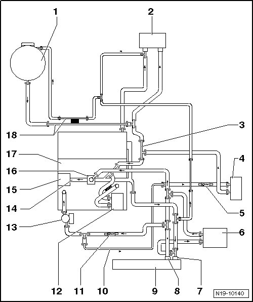
1 Expansion Tank
2 Heater Core
• Replace the coolant after replacing.
3 Coolant Pipe, Side, Top
4 Transmission Fluid Cooler
5 Check Valve
• Pay attention to the installed position.
• The arrow on the check valve points in the direction of flow.
6 Auxiliary Cooler
• Not installed
7 Upper Coolant Hose
8 Lower Coolant Hose
9 Radiator
10 Coolant Pipe, Side, Bottom
11 Check Valve
• Pay attention to the installed position.
• The arrow on the check valve points in the direction of flow.
12 Engine Oil Cooler
13 Recirculation Pump (V55)
14 Coolant Pipe
• With the coolant thermostat housing.
15 Coolant Pump
16 Coolant Thermostat
17 Cylinder Block
18 Rear Coolant Pipe