Version II
1992 m.y., With Trip Computer Range Calibration On Left Side Of Instrument Cluster
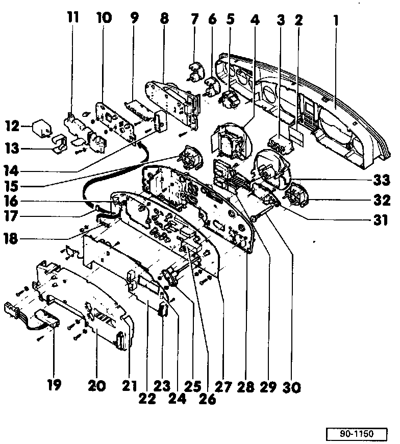
1 Front frame with glass (plastic housing)
2 Symbol plate
3 Warning light housing
4 Speedometer
5 Analog clock
6 Oil temperature gauge
7 Oil pressure gauge
8 Instrument support (side panel)
9 Warning light housing (side panel)
10 Printed circuit (side panel)
11 Cover (side panel)
12 Radio/parking light warning buzzer -J152-
13 Warning buzzer bracket
14 Gear selector display
15 Fuel gauge
16 Multi-pin connector, red (instrument panel wiring harness)
17 Six-pin connector for printed circuit (side panel)
18 Voltage stabilizer with heat sink
19 Outside temperature display with 5-pin connector
20 Cover
21 Opening for adjusting trip computer range calibration
22 Printed circuit for Auto-check system and trip computer
• With fuel consumption correction switch and country code switch
23 Coding connector (plug) for trip computer
24 Trip computer potentiometer (range calibration)
25 Instrument panel light dimmer switch
26 Multi-pin connector, green (instrument panel wiring harness)
27 Printed circuit
28 Instrument support
29 Mini-check/Auto-check/trip computer display unit
30 Adjusting knob
• For instrument panel light dimmer switch/button for Auto- Check system
31 Digital clock
• Only with tachometer and with- out auxiliary instruments
• Not on USA vehicles
32 Coolant temperature gauge
33 Tachometer or analog clock