Camshaft Position Sensor: Service and Repair
Camshaft Position Sensor Seal
Special tools, testers and auxiliary items required
• Seal puller - general usage (2085)
• Seal installer (3241)
Removing
Left Cylinder Head
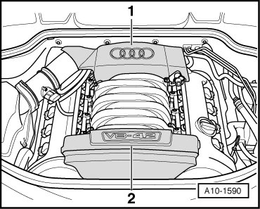
- Remove the engine cover - 1 - upward.
- Remove the left combination valve for the Secondary Air Injection (AIR) system. Refer to => [ Secondary Air Injection (AIR) Combination Valve ] Left Side Components.
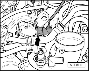
- Disconnect the electrical connector - arrow - from the Camshaft Position (CMP) sensor 2 (G163).
- Remove the CMP sensor bolts.
- Remove the CMP sensor washer and cover.
Right Cylinder Head
- Remove the engine cover - 2 - upward.
- Pull the lock carrier toward the front. Refer to => [ Lock Carrier, Pulling Toward the Front ] Lock Carrier, Pulling Toward the Front.
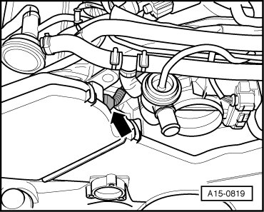
- Disconnect the electrical connector - arrow - from the CMP sensor (G40).
- Remove the right toothed belt guard.
- Remove the bolts - arrows -.
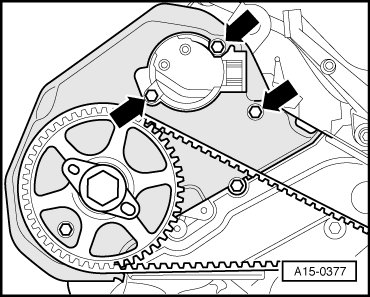
- Pull the toothed belt guard slightly toward the front and remove the CMP sensor.
- Remove the CMP sensor washer and cover.
Continuation for Both Sides
• In the following illustrations, the right cylinder head is shown.
- To guide the (2085), thread the (2085/1) into the camshaft by hand until seated.
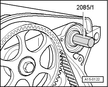
- Loosen the inner portion of the (2085) two rotations from the outer portion and secure with the knurled screw.
- Grease the threaded head of the (2085), position and screw into the oil seal as far as possible with forced pressure.
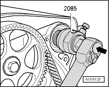
- Loosen the knurled screw and turn the inner part against the camshaft until the seal is removed.
- Place the (3241/2) on the camshaft.
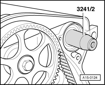
- Push the seal over the (3241/2).
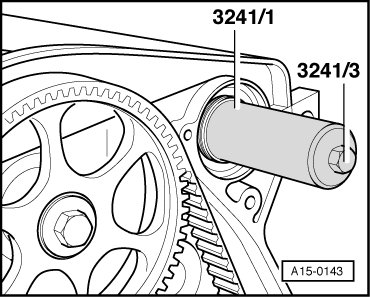
- Press in the seal until seated using the (3241/1). To do so, use the (3241/3).
Further installation is performed in reverse order of removal, noting the following:
• Replace the O-ring.
• Secure all hose connections using hose clamps appropriate for the model type.
• Hose connections and charge air system hoses must be free of oil and grease before installing. Do not use lubricant under any circumstances.
Left Cylinder Head
- Install the left combination valve for the AIR system. Refer to => [ Secondary Air Injection (AIR) Combination Valve ] Left Side Components.
Right Cylinder Head
- Install the lock carrier with attachments.
Tightening Specifications
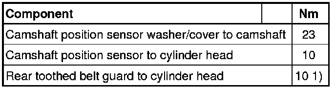
• 1) Insert using locking compound