Camshaft Position Sensor 1, Checking
Camshaft Position Sensor 1, Checking
Special tools, testers and auxiliary items required
• multimeter
• Voltage Tester
• connector test kit
• test box
Both camshaft position (CMP) sensors supply the Engine Control Module (ECM) with the position of intake camshafts.
• Camshaft Position (CMP) Sensor (G40) is located at front of right cylinder head (bank 1).
Test requirement:
• Ignition switched off.
- Remove air filter housing.
Checking activation
- Connect voltage tester with measuring probes and connector adapters between terminal 2 (CMP sensor signal) and terminal 1 (+5 V); the harness connector remains connected.
• Connector sockets are numbered respectively on the rear side of the connector.
- Operate starter for a few seconds.
LED must blink.
• Voltage testers do not go out completely during low current pick-up between activations by the ECM, but rather continue to glow a little and then get significantly brighter during activation.
- Switch ignition off.
If LED does not blink:
Checking voltage supply
- Disconnect electrical harness connector from Camshaft Position (CMP) Sensor (G40).
- Connect multimeter for voltage measurement as follows:
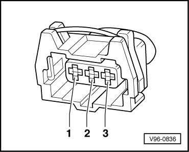

- Switch ignition on.
Specified value: about 5 V
- Switch ignition off.
Checking signal wire
- Connect multimeter for voltage measurement as follows:

- Switch ignition on.
Specified value: approx. +5 V
- Switch ignition off.
Checking Ground (GND) wire
- Connect multimeter for voltage measurement as follows:

Specified value: approx. +5 V
If all specified values are being reached and the LED does not blink (measured between terminal 1 and 2 with starter and connector connected):
- Replace Camshaft Position (CMP) sensor.
If specified values are not obtained:
Checking wire connections between Camshaft Position (CMP) sensor and Engine Control Module (ECM)
- Connect test box to wiring harness of Engine Control Module (ECM) ; ECM is not connected.
- Check the following wire connections for open circuit according to wiring diagram:
• Camshaft Position (CMP) Sensor (G40) (bank 1)
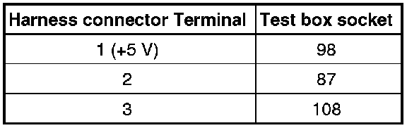
Specified value: Wire resistance max 1.5 ohms
- Check wires for short circuit to each other as well as to B+ and Ground (GND).
Specified value: infinite ohms (no continuity)
- If necessary, repair wire connection.
Final procedures
- Install air filter housing.
After repair work, the following work steps must be performed in the mentioned sequence:
1. Check DTC memory => [ Diagnostic Mode 03 - Read DTC Memory ] Diagnostic Mode 03 - Read DTC Memory.
2. If necessary, erase DTC memory => [ Diagnostic Mode 04 - Erase DTC Memory ] Diagnostic Mode 04 - Erase DTC Memory.
3. If DTC memory was erased, generate readiness code.