Knock Sensor: Testing and Inspection
Knock Sensors, Checking
Special tools, testers and auxiliary items required
• multimeter
• connector test kit
• Cylinders 1, 2, 3 and 4 are monitored by Knock Sensor (KS) 1 (G61). Cylinders 5 and 6 are monitored by Knock Sensor (KS) 2 (G66). Cylinders 7 and 8 are monitored by Knock Sensor (KS) 3 (G198).
• Knock Sensor (KS) 1 (G61), Knock Sensor (KS) 2 (G66), and Knock sensor 3 (G198) themselves cannot be electrically tested.
• When servicing terminals in harness connector of knock sensors, use only gold-plated terminals.
• For the knock sensors to function properly, it is important that tightening torque be exactly 20 Nm.
• Check harness connector from knock sensor to wiring harness for corrosion.
Test procedure
- Perform a preliminary check to verify the customers complaint. Refer to => [ Preliminary Check ] Preliminary Check.
• Ignition switched off.
- Remove air filter housing.
Checking knock sensor wiring
- Disconnect electrical harness connector of respective knock sensor.
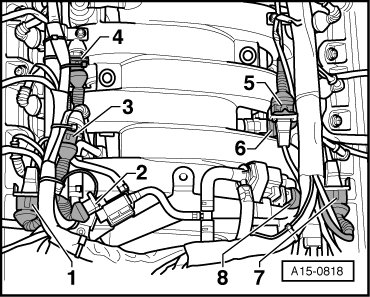
1 Knock Sensor (KS) 1 (G61)
5 Knock Sensor (KS) 3 (G198)
7 Knock Sensor (KS) 2 (G66)
4 Knock Sensor (KS) 4 (G199)
• Disregard the other items.
- Check all three terminals at knock sensor for short circuit to each other (terminal 1+2, 1+3, 2+3).
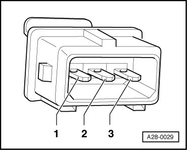
Specified value: infinite ohms (no continuity) - the wires must not have any connection to each other.
- If there is a connection, replace knock sensor.
If no malfunction can be found:
Check wires from knock sensors to Engine Control Module (ECM).
- Connect test box to wiring harness of Engine Control Module (ECM) ; ECM is not connected.
- Check the following wire connections for open circuit according to wiring diagram:
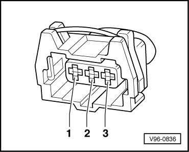
• Knock Sensor (KS) 1 (G61)and Knock Sensor (KS) 2 (G66) monitor cylinders 1,2,3, & 4.

• Knock Sensor 3 (G198) and Knock Sensor 4 (G199)monitor cyl. 5,6,7, and 8.

• Knock Sensor 3 (G198) (bank 2, cyl. 7 and 8)


Specified value: Wire resistance max 1.5 ohms
- Check wires for short circuit to each other as well as to B+ and Ground (GND).
Specified value: infinite ohms (no continuity)
- If necessary, repair wire connection.
Final procedures
- Install air filter housing.
After repair work, the following work steps must be performed in the mentioned sequence:
1. Check DTC memory => [ Diagnostic Mode 03 - Read DTC Memory ] Diagnostic Mode 03 - Read DTC Memory.
2. Erase DTC memory => [ Diagnostic Mode 04 - Erase DTC Memory ] Diagnostic Mode 04 - Erase DTC Memory
3. If DTC memory was erased, generate readiness code.