Oxygen Sensor and Sensor Control Before Catalytic Converter, Checking
Oxygen Sensor and Sensor Control before Catalytic Converter, Checking
Special tools, testers and auxiliary items required
• Multimeter (V.A.G 1526 A)
• Connector test kit (V.A.G 1594 A)
• Test box (VAG1598/31)
• Vehicle diagnostic, testing and information system ( VAS 5051)
• Adapter (VAS 5051/1)
Requirements
• No leaks in exhaust system
• Coolant temperature at least 80 °C.
Work sequence
- Connect vehicle diagnostic, testing and information system (VAS 5051) and select vehicle system "01 -Engine electronics" in selection. Refer to => [ VAS5051, Connecting and Selecting Functions ] VAS 5051, Connecting and Selecting Functions. Engine must be run at idle speed.
Display on (VAS 5051):
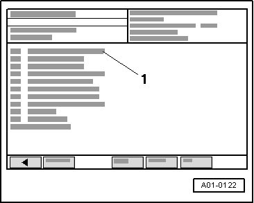
- Under - 1 - select diagnostic function "04 - Basic setting".
Display on (VAS 5051):
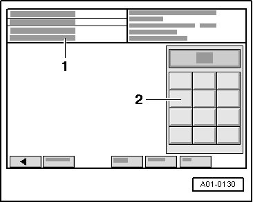
1. Enter display group
- Enter "030" for "display group number 030" in field - 2 - and confirm entry by pressing Q button.
Display on (VAS 5051):
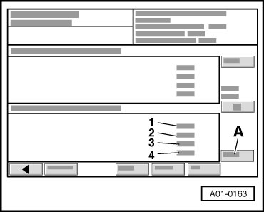
- Activate basic setting by pressing A button.
- Check specification in display field - 1 -.
• By increasing the engine speed the specified values are achieved more quickly.
• The "Oxygen Sensor status" indicates the condition of the Oxygen Sensor control and the Oxygen Sensor (O2S).
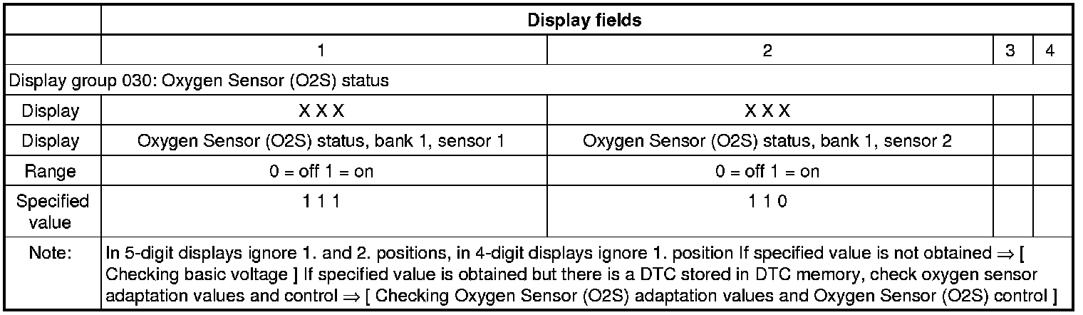

• The first digit of the 3-digit display (heating) fluctuates between 0 and 1.
Display on (VAS 5051):
- Only continue test if display in display field - 1 - has reached "111" at least once.
- Press arrow button.
Checking Oxygen Sensor (O2S) adaptation values and Oxygen Sensor (O2S) control
Display on (VAS 5051):
1. Enter display group
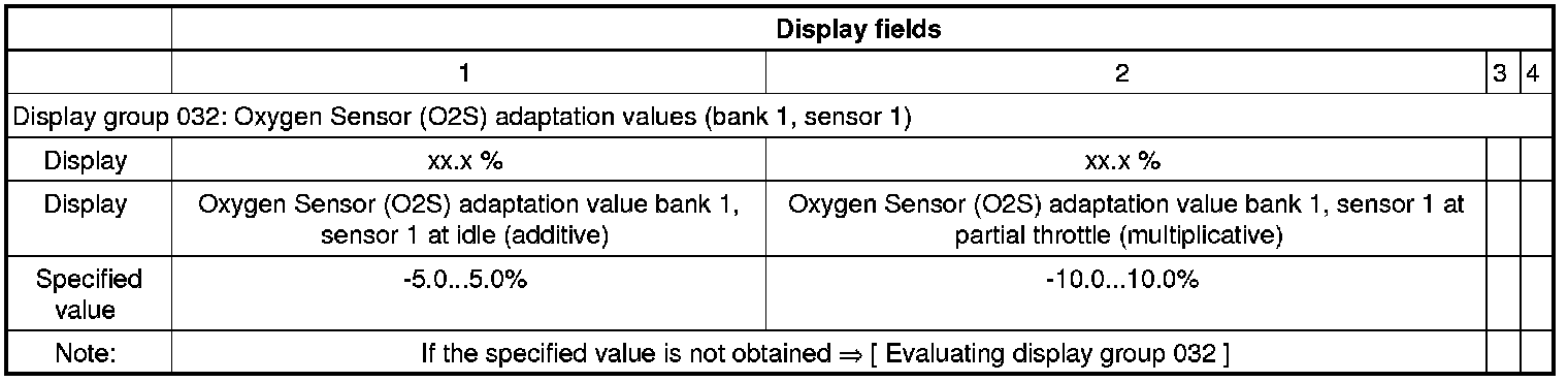
- Enter "032" for "display group number 032" in field - 2 - and confirm entry by pressing Q button.
Display on (VAS 5051):
- Activate basic setting by pressing A button.
- Check indication in display groups - 1 -and - 2 -.
- Press arrow button.
Display on (VAS 5051):
1. Enter display group
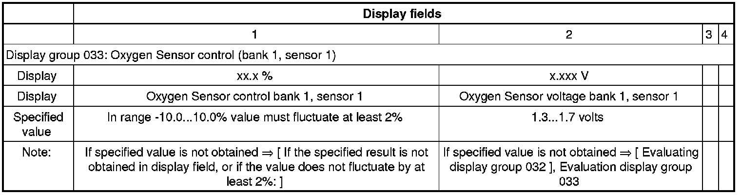
- Enter "033" for "display group number 033" in field - 2 - and confirm entry by pressing Q button.
Display on (VAS 5051):
- Activate basic setting by pressing A button.
- Check indication in display groups - 1 -and - 2 -.
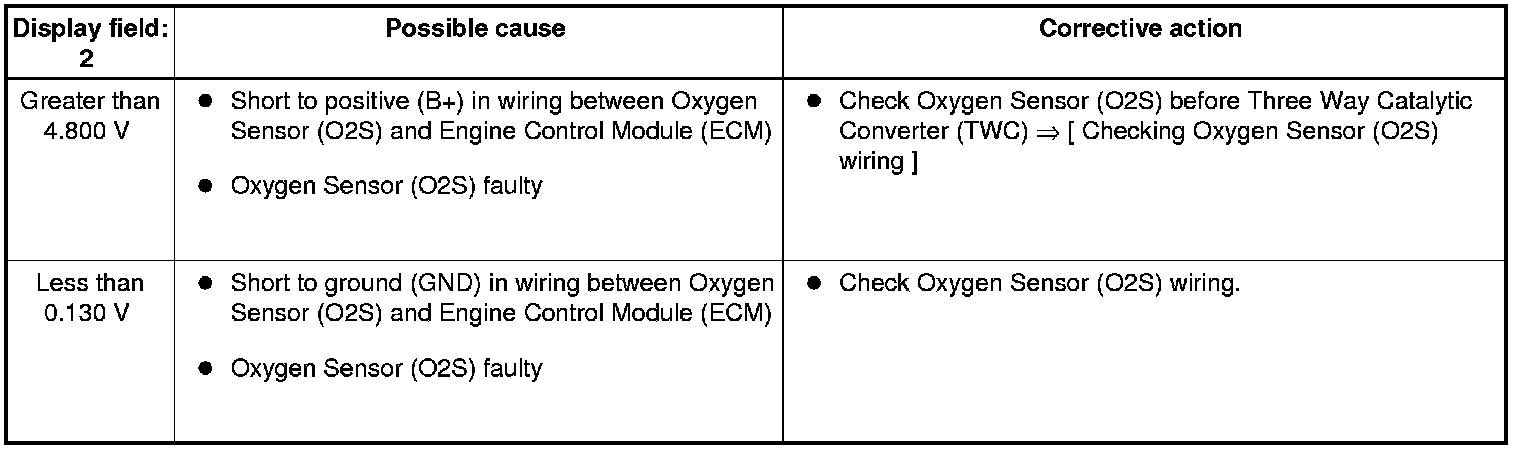
• Note on display field 2:
• Displayed is the Oxygen Sensor (O2S) voltage signal which was prepared and smoothed in the Engine Control Module (ECM). 1.5 V in the display corresponds to Oxygen Sensor (O2S) 1.
If the specified result is not obtained in display field, or if the value does not fluctuate by at least 2%:
- Perform test drive to free Oxygen Sensor (O2S) from any possible residues and repeat test.
If the specified result is not obtained in display field 1 3, or if the value does not fluctuate by at least 2%, even after the test drive:
- Check basic voltage.
- Check Oxygen Sensor (O2S) before Three Way Catalytic Converter (TWC) heating. Refer to => [ Oxygen Sensor Heater before Catalytic Converter, Checking ] Oxygen Sensor Heater Before Catalytic Converter, Checking.
- Check Oxygen Sensor (O2S) before Three Way Catalytic Converter (TWC) aging. Refer to => [ Oxygen Sensor before Catalytic Converter, Checking ] Oxygen Sensor Before Catalytic Converter, Checking.
Evaluating display group 032
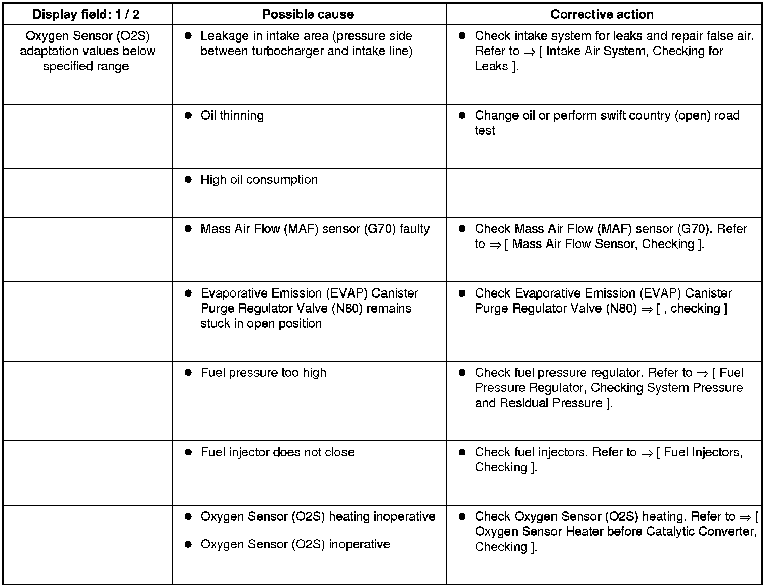
Evaluating display group 032
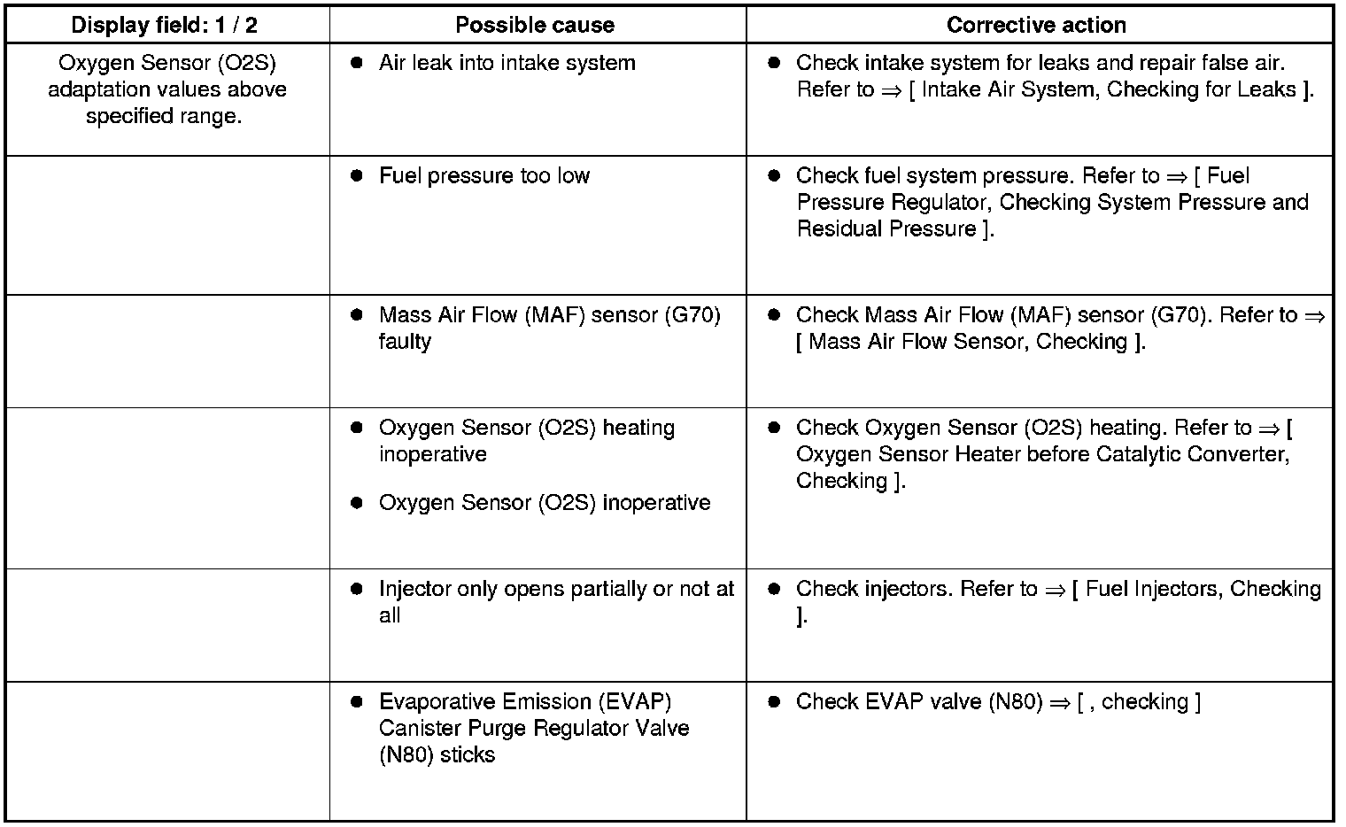
Evaluating display group 033
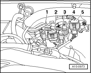
Checking basic voltage
- Disconnect 6-pin connector (black) - 5 - to Oxygen Sensor (O2S) before Three Way Catalytic Converter (TWC).
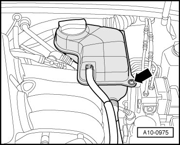
• To gain access to the connector, remove coolant expansion tank bolt (arrow) and move expansion tank to side. Fuel hoses remain connected.
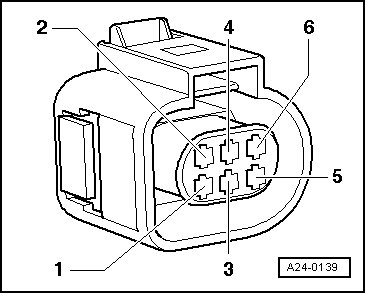
- Connect multimeter between terminals 1 and 5 to measure voltage.
- Switch ignition on.
• Specified value: 0.400...0.500 V
- Switch ignition off.
If specified value is not obtained:
- Check Oxygen Sensor (O2S) wiring.
If specified value is obtained:
- Replace Oxygen Sensor (O2S) before Three Way Catalytic Converter (TWC).
Checking Oxygen Sensor (O2S) wiring
- Disconnect 6-pin connector (black) - 5 - to Oxygen Sensor (O2S) before Three Way Catalytic Converter (TWC).
• To gain access to the connector, remove coolant expansion tank bolt (arrow) and move expansion tank to side. Fuel hoses remain connected.
- Connect test box (VAG1598/31) to wiring harness for ECM; do not connect ECM. Refer to => [ Electrical Testing, with Test Box VAG 1598/31 ] Electrical Testing, With Test Box VAG 1598/31.
- Test for open circuit in the following wiring connections.
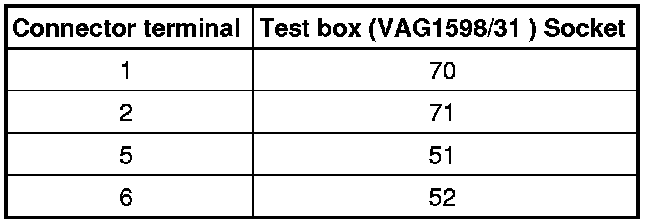
- Repair open circuit, if necessary.
- Check for shorts between two wires.
If the wiring is OK:
- Replace ECM. Refer to => [ Engine Control Module without Metal Anti-Theft Housing, Replacing ] Engine Control Module Without Metal Anti-Theft Housing, Replacing.