Multi-Function Transmission Range Switch, Checking
Multi-Function Transmission Range Switch, Checking
• Before performing the electrical test on the Multifunction Transmission Range (TR) Switch, you must first check the Measured Value Block for the multifunction switch => [ Reading Measured Value Block ] Reading Measured Value Block, display ground number 004
• Make sure that the selector lever cable is correctly adjusted.
Functional Test
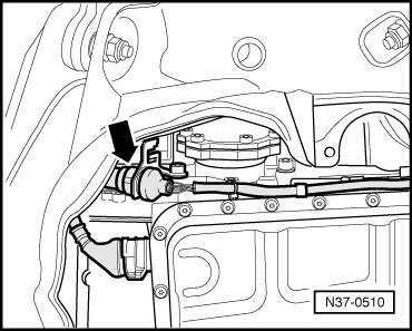
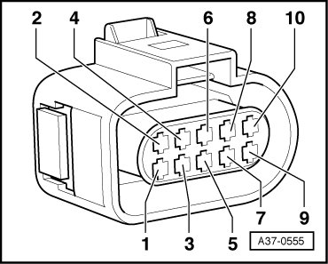
- Disconnect connector - arrow - for Multi-function Transmission Range (TR) Switch (F125) at front left of transmission.
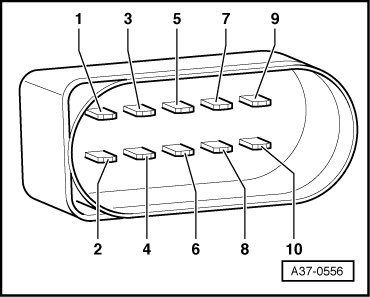
Terminal pinout at the connector for Multi-function Transmission Range (TR) Switch (F125).
Test Step 1:
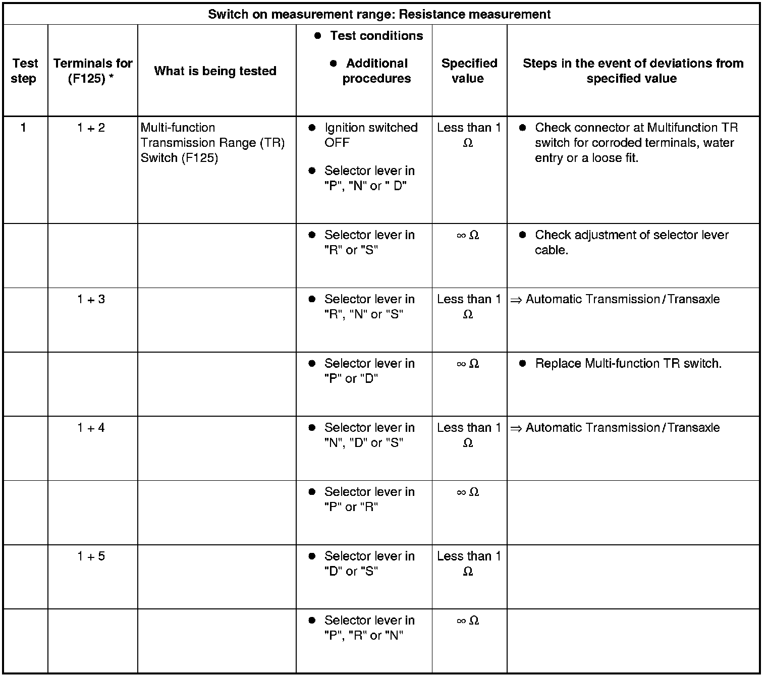
* Terminal pinout at the connector for Multi-function TR switch
Test Step 2-3:
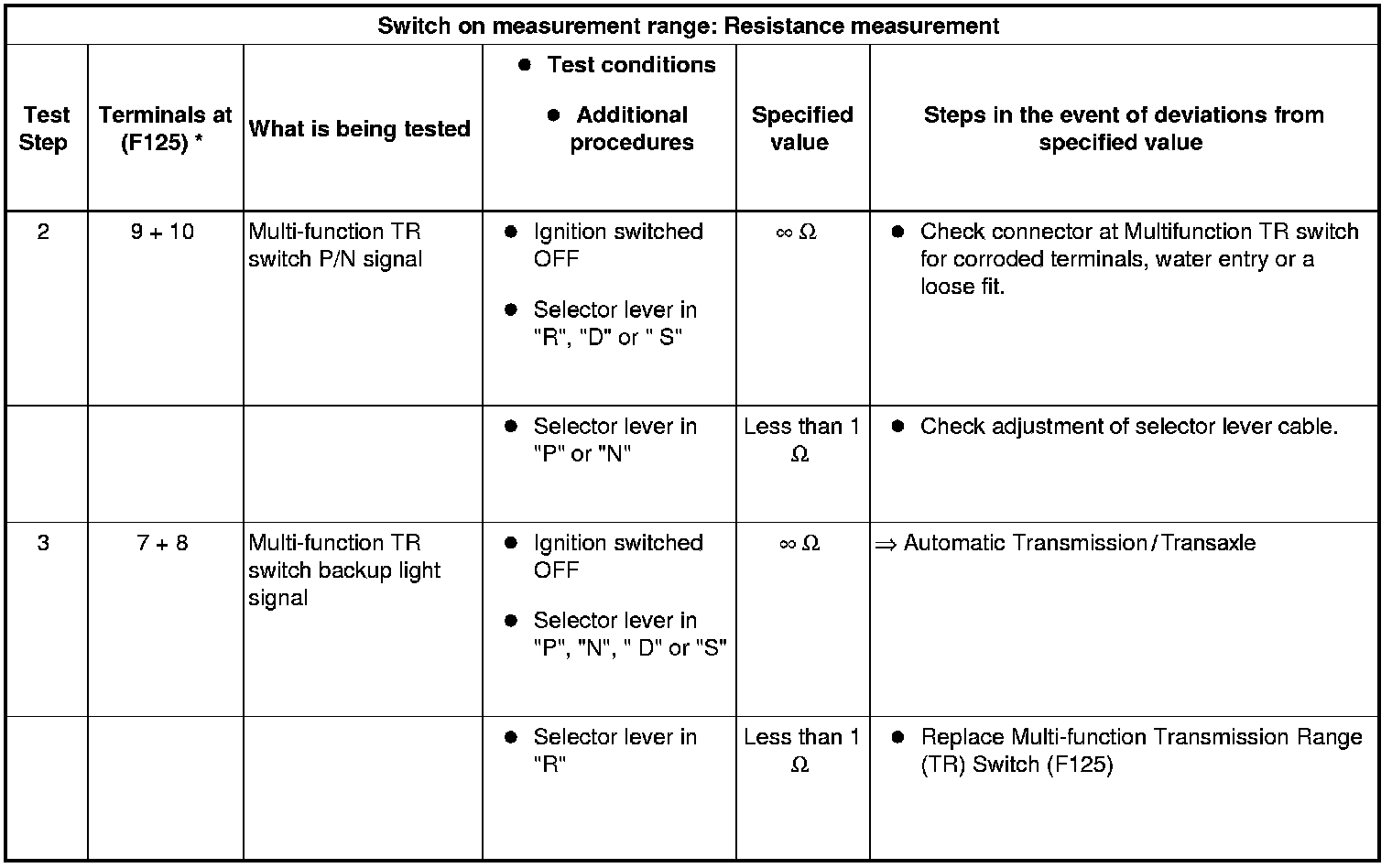
* Terminal pinout at the connector for Multi-function TR switch
Check Power Supply to Multi-Function TR Switch
- Attach Multimeter for a voltage measurement between following terminals of 10-pin connector.
- Switch ignition ON.
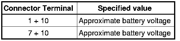
If a specified value is not reached:
- Repair open circuit or short circuit as necessary.
Check Wiring Connection Between 10-pin Connector for Multi-Function Switch and Transmission Control Module (TCM
- Remove Transmission Control Module (TCM) => [ Transmission Control Module ] Service and Repair and separate multiple connector => Service and Repair.
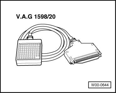
- Connector Test box (VAG1598/20) to control module wiring harness.
- Connect multimeter to make a resistance measurement between terminals of 10-pin connector and cavities of test box (VAG1598/20 ), as described in following chart:
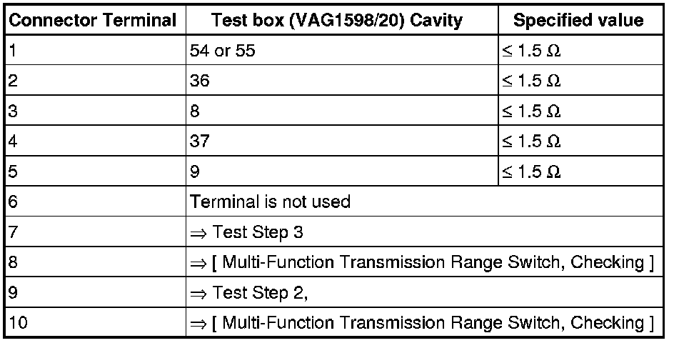
• In the event of deviations from the specified value, repair open circuit following wiring diagram and check connector for corroded terminals, water entry and leakage.
• If this test revealed no unacceptable deviations, Multi-function Transmission Range Switch (F125) must be replaced.