Fuel Metering Valve, Checking
Fuel Metering Valve, Checking
Special tools, testers and auxiliary items required
• Multimeter.
• Wiring diagram.
Test requirements
• Fuel Pump (FP) Control Module (J538)OK
• Fuses for engine electronics OK.
• Fuel filter OK.
• Parking brake engaged.
• Battery voltage at least 12.5 V.
• Vehicles with automatic transmission, shift selector lever into position "P" or "N".
• All electrical consumers such as, lights and rear window defroster, switched off (radiator fan must not run during test).
• A/C switched off.
• The fuel tank at least 1/4 full.
• Ignition switched off.
Test procedure
- Perform a preliminary check to verify the customer's complaint. Refer to => [ Preliminary Check ] Preliminary Check.
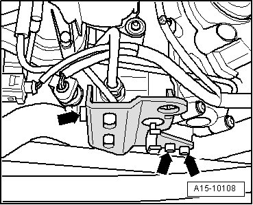
- Remove three screws - arrows - and the engine lifting eye to gain access to the electrical harness connector.
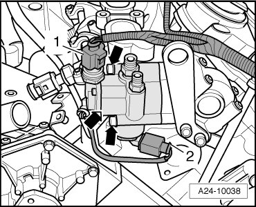
- Disconnect the Fuel Metering Valve (N290)electrical harness connector - 2 - from the Fuel Metering Valve (N290).
Checking internal resistance
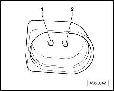
- Using a Multimeter , check the Fuel Metering Valve (N290) terminals for resistance.

Specified value: 450 to 1000 ohms.
If specified value is not obtained:
- Replace the Fuel Metering Valve (N290)
If specified value is obtained:
Checking voltage
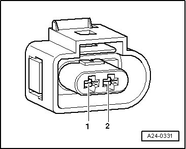
- Using a Multimeter , check the wiring connection from the Fuel Metering Valve (N290)electrical harness connector terminals for voltage.

- Operate the starter briefly.
Specified value: Battery voltage.
- Switch the ignition off.
If there is no voltage:
Checking wiring connections
If the manufacturers test box is being used, perform the following step.
- Connect the Test Box 105 Pin (VAG1598/42) with Adapter Cable (1598/39-1).
If the manufacturers test box is not being used, perform the following step.
- Remove the Engine Control Module (ECM) (J623) => [ Engine Control Module, Replacing ] Engine Control Module, Replacing.
- Using a Multimeter , check the following wire connections for an open circuit.


Specified value: 1.5 ohms max.
If the specification is not obtained:
- Check the wiring for a short circuit to Battery positive (+) or an open circuit.
If specified value is not obtained:
- If necessary, repair the wiring connection.
If no malfunctions are found in wiring:
- Replace the Engine Control Module (ECM) (J623).
- Assembly is performed in the reverse of the removal.
After repair work, the following work steps must be performed in the following sequence:
1. Check the DTC memory. Refer to => [ Diagnostic Mode 03 - Read DTC Memory ] Diagnostic Mode 03 - Read DTC Memory.
2. If necessary, erase the DTC memory. Refer to => [ Diagnostic Mode 04 - Erase DTC Memory ] Diagnostic Mode 04 - Erase DTC Memory.
3. If the DTC memory was erased, generate readiness code. Refer to => [ Readiness Code ] Monitors, Trips, Drive Cycles and Readiness Codes.