Shift Lock Solenoid, Checking
Shift Lock Solenoid, Checking
Special tools, testers and auxiliary items required
• Multimeter.
• Wiring diagram.
Test requirements
• Fuse (S13) OK.
• Brake Light Switch (F) OK.
• The ignition switched off.
Test procedure
- Perform a preliminary check to verify the customer's complaint. Refer to => [ Preliminary Check ] Preliminary Check.
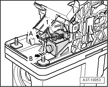
- Disconnect the Shift Lock Solenoid (N110) electrical harness connector- 1 - by releasing the catches- arrow A - and pulling away from the solenoid- arrow B -
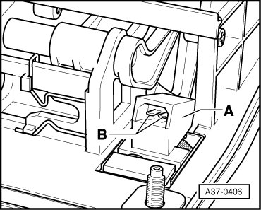
Checking internal resistance
- Using a Multimeter, check the Shift Lock Solenoid (N110) terminals 1 and 2 - B -for resistance.
Specified value: 21.3 to 23.3 ohms.
If the specified value is not obtained:
- Replace the Shift Lock Solenoid (N110).
If the specification is obtained:
Checking voltage supply
- Using a Multimeter, check the Shift Lock Solenoid (N110) terminal T2l/1 to Ground (GND) for voltage.
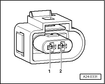

- Switch the ignition on.
- Depress the brake pedal.
Specified value: battery voltage.
- Release the brake pedal.
Specified value: 0V.
- Switch the ignition off.
If the specified value was not obtained:
- Check the wiring connection from the Transmission Control Module (TCM) (J217) electrical connector T20e/5 terminal to the Shift Lock Solenoid (N110) electrical harness connector terminal T2l/1 to for an open circuit or a short to Battery positive (+).

If the specified value was not obtained:
- Check the electrical harness connector for damage, corrosion, loose or broken terminals.
- If necessary, repair the wiring connection.
If the specified value was obtained:
Check Ground (GND) activation
- Using a Multimeter, check the Shift Lock Solenoid (N110) electrical harness connector terminal T2l/2 to Battery (+) for voltage.

- Switch the ignition on.
Specified value: battery voltage.
- Switch the ignition off.
If the specified value was not obtained:
- Check the wiring connection from the Shift Lock Solenoid (N110) electrical harness connector terminal T2l/2 to ground connection 8 (in the main wiring harness) for an open circuit or a short to Battery positive (+).
- Check the electrical harness connector for damage, corrosion, loose or broken terminals.
- If necessary, repair the wiring connection.
If the specified value was obtained:
Checking wiring
If the manufacturers test box is being used, perform the following step.
- Install the test box (VAG1598/31).
If the manufacturers test box is not being used, perform the following step.
- Remove the Transmission Control Module (TCM) (J217). Refer to => [ Transmission Control Module, Replacing ] Service and Repair.
- Using a Multimeter, check the Shift Lock Solenoid (N110) terminal T2am1 to the Brake Light Switch (F) electrical connector terminal 4
- Using a Multimeter, check the Shift Lock Solenoid electrical connector terminals T2am2 to Transmission Control Module (TCM) (J217) electrical connector terminal 7 for an open circuit.

Specified value: 1.5 ohms max.
If the specification is not obtained:
- Check the wiring for a short circuit to each other, to Battery positive (+), Ground (GND) or an open circuit.
- Check the electrical harness connector for damage, corrosion, loose or broken terminals.
- If necessary, repair the wiring connection.
- Erase the DTC memory. Refer to => [ Diagnostic Mode 04 - Erase DTC Memory ] Diagnostic Mode 04 - Erase DTC Memory.
- Perform a road test to verify repair.
If the DTC does not return:
Repair complete, Generate readiness code. Refer to => [ Readiness Code ] Monitors, Trips, Drive Cycles and Readiness Codes.
- End diagnosis.
If the DTC does return and no malfunction is detected in the wiring and the voltage supply was OK:
- Replace the Transmission Control Module (TCM) (J217). Refer to => [ Transmission Control Module, Replacing ] Service and Repair.
- Assembly is performed in the reverse of the removal.
After the repair work, the following work steps must be performed in the following sequence:
1. Check the DTC memory. Refer to => [ Diagnostic Mode 03 - Read DTC Memory ] Diagnostic Mode 03 - Read DTC Memory.
2. If necessary, erase the DTC memory. Refer to => [ Diagnostic Mode 04 - Erase DTC Memory ] Diagnostic Mode 04 - Erase DTC Memory.
3. If the DTC memory was erased, generate readiness code. Refer to => [ Readiness Code ] Monitors, Trips, Drive Cycles and Readiness Codes.