Tiptronic Switch, Checking
Tiptronic Switch, Checking
• The Selector Lever Sensor System Control Module (J587)and the Tiptronic Switch (F189) are combined into one component.
Special tools, testers and auxiliary items required
• Multimeter
• Wiring diagram
Requirements
• Fuses (SB15 and SA20) OK.
• Selector Lever Sensor System Control Module (J587)must be OK.
• The Control Module with indicator unit in the Instrument Cluster Control Module (J285) must be OK.
• The selector lever cable adjustment OK.
• The battery voltage must be at least 12.5 V.
• All electrical consumers must be switched off.
• The parking brake must be engaged.
• The selector lever must be in the "P" position.
• The Ground (GND) connections to transmission must be OK.
Procedure
- Switch the ignition on.
- Depress the brake pedal and maintain depressed.
- Shift the selector lever into all positions.
The selector lever position must correspond with the Tiptronic Switch (F189) indicator display unit.
- Switch the ignition off.
If the selector lever position does not correspond with the Tiptronic Switch (F189) indicator display unit:
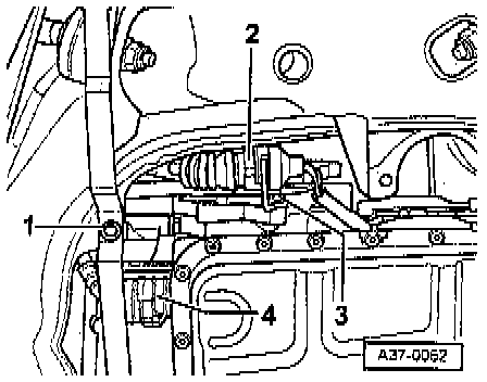
- Disconnect the Tiptronic Switch (F189) electrical harness connector - 2 -.
- Check the electrical harness connector for damage, corrosion, loose or broken terminals.
- Repair any damage found to the electrical harness connector.
If the electrical harness connector is not OK:
- Repair the malfunction.
If the electrical harness connector is OK:
Checking voltage
- Switch the ignition on.
- Using a multimeter, check the Tiptronic Switch (F189) electrical harness connector terminal T10p/7 to Ground (GND) for voltage.
Specified value, Battery voltage.
- Switch the ignition off.
If the specified value was not obtained:
- If necessary, repair the faulty wiring connection.
If the specified value was obtained:
Checking Ground (GND)
- Using a multimeter, check the Tiptronic Switch (F189) electrical harness connector terminal 10p/6 to Ground (GND) connection for resistance.
Specified value: 1.5 ohms Max.
If the specification was not obtained:
- Check the wiring for a short circuit to each other, Battery (+), and Ground (GND).
- If necessary, repair the faulty wiring connection.
If no malfunction was found in the wiring and the resistance was OK:
Checking wiring
- Remove the Transmission Control Module (TCM) (J217). Refer to => [ Transmission Control Module, Replacing ] Service and Repair.
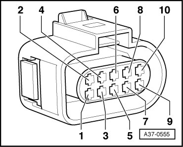
- Using a multimeter, check the Tiptronic Switch (F189) electrical harness connector terminals to the Transmission Control Module (TCM) (J217) electrical harness connector terminals for an open circuit.
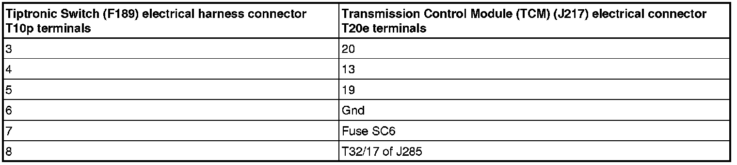
Specified value: 1.5 ohms Max.
If the specification was not obtained:
- Check the wiring for a short circuit to each other, Battery (+), and Ground (GND).
- If necessary, repair the faulty wiring connection.
If no malfunction was found in the wiring and the resistance was OK:
- Replace the Transmission Control Module (TCM) (J217). Refer to=> [ Transmission Control Module, Replacing ] Service and Repair.
- Assembly is performed in the reverse of the removal.
1. Check the DTC memory. Refer to => [ Diagnostic Mode 03 - Read DTC Memory ] Diagnostic Mode 03 - Read DTC Memory.
2. If necessary, erase DTC memory of the Transmission Control Module (TCM) (J217). => [ Diagnostic Mode 04 - Erase DTC Memory ] Diagnostic Mode 04 - Erase DTC Memory.
3. Generate readiness code. => [ Readiness Code ] Monitors, Trips, Drive Cycles and Readiness Codes.