Ignition System: Service and Repair
Ignition System Assembly Overview
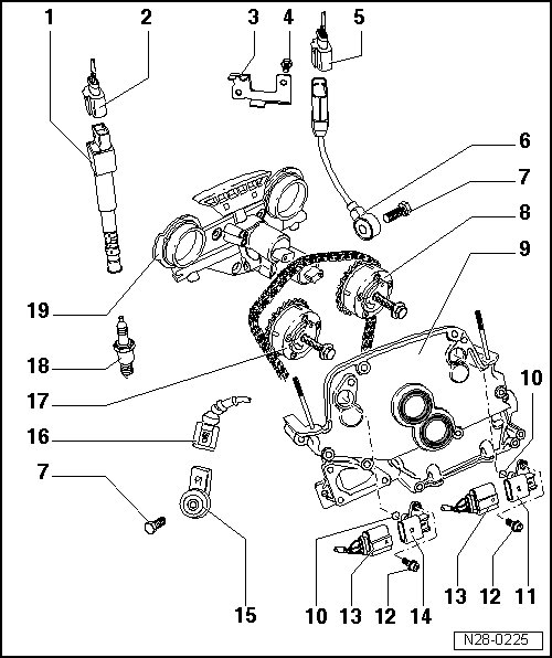
1 Ignition coils with power output stages
• Cylinder 1 Ignition Coil 1 with Power Output Stage (N70)
• Cylinder 2 Ignition Coil 2 with Power Output Stage (N127)
• Cylinder 3 Ignition Coil 3 with Power Output Stage (N291)
• Cylinder 4 Ignition Coil 4 with Power Output Stage (N292)
• Cylinder 5 Ignition Coil 5 with Power Output Stage (N323)
• Cylinder 6 Ignition Coil 6 with Power Output Stage (N324)
• Removing and installing => [ Ignition Coils ] Service and Repair
2 4-pin harness connector
• For ignition coils with power output stage
3 Bracket
• For Knock Sensor (KS) 1 (G61) connector
4 Bolt - 10 Nm
5 3-pin harness connector
• Black
• With gold-plated terminals
6 Knock Sensor (KS) 1 (G61)
7 Bolt - 20 Nm
• For trouble-free knock sensor function, it is important to use the exact tightening specifications
8 Camshaft adjuster
• Exhaust side
• With sensor wheel for Camshaft Position (CMP) Sensor 2 (G163)
9 Top cover for camshaft timing chain
• Removing and installing
10 Seal
• Replace
11 Camshaft position (CMP) sensor 2 (G163)
• For exhaust camshaft
12 Bolt - 10 Nm
13 3-pin harness connector
• Black
• With gold-plated terminals
14 Camshaft Position (CMP) sensor (G40)
• For intake camshaft
15 Knock Sensor (KS) 2 (G66)
16 2-pin harness connector
• Black
• With gold-plated terminals
17 Camshaft adjuster
• Intake side
• With sensor wheel for Camshaft Position (CMP) Sensor (G40)
• After reinstalling, adjust valve timing
18 Spark plug
• Current values
19 Control housing
• For camshaft adjustment
• Removing and installing