Rear Subframe: Service and Repair
Subframe Assembly Overview
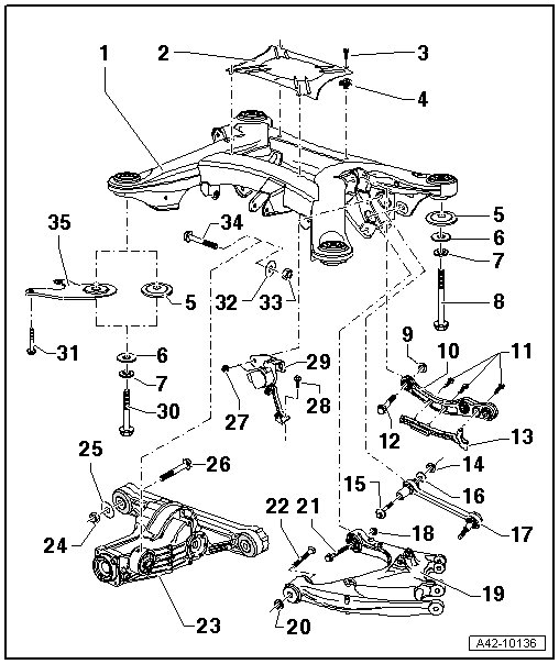
1 Subframe
• Removing and installing, refer to => [ Subframe ] Subframe.
• Do not raise the vehicle using the subframe.
2 Cover
• The arrow on the cover points in the direction of vehicle travel.
3 Bolt, 3 Nm
4 Nut
5 Washer
6 Washer
7 Tension Disc
• Always replace.
• The detent edges face toward the bolt head.
8 Bolt
• The length of the bolt depends on the Vehicle Identification Number (VIN). Always check the VIN when replacing.
• First tighten all the bolts to 50 Nm. Then tighten all the bolts to 150 Nm and 90° additional turn.
• Always replace.
• The threaded plate in the body can be replaced.
9 Self Locking Nut
• Always replace.
10 Track Control Arm
• Removing and installing, refer to => [ Track Control Arm ] Track Control Arm.
11 Bolt, 4 Nm
12 Bolt, 80 Nm + 90° additional turn
• Always replace.
13 Wire Channel
14 Self Locking Nut, 95 Nm
• Always replace.
• Raise the wheel bearing housing before tightening. Refer to => [ Wheel Bearing Housing, Raising to Control Position to Tighten Bolts ] Procedures, (except for vehicle alignment).
15 Eccentric Bolt
• Adjust the toe after loosening. Refer to => [ Rear Toe, Adjusting ] Rear Toe, Adjusting.
• Do not turn more than 90° right or left (that is smallest to largest possible adjustment).
16 Eccentric Washer
• Inner bore with tab.
17 Tie Rod
• Removing and installing, refer to => [ Tie Rod ] Tie Rod.
• The tie rod must be replaced if it was loosened from the connecting link - item 20 - in => [ Stabilizer Bar, Track Control Arm, Tie Rod, Coupling Rod, Connecting Link, Trailing Arm and Level Control System Sensor Assembly Overview ] Stabilizer Bar, Track Control Arm, Tie Rod, Coupling Rod, Connecting Link, Trailing Arm and Level Control System Sensor Assembl.
18 Self Locking Nut, 80 Nm + 90° additional turn
• Always replace.
• Raise the wheel bearing housing before tightening. Refer to => [ Wheel Bearing Housing, Raising to Control Position to Tighten Bolts ] Procedures.
19 Trailing Arm
20 Self Locking Nut
• Always replace.
21 Bolt
• Always replace.
22 Bolt, 80 Nm + 90° additional turn
• Always replace.
• Raise the wheel bearing housing before tightening. Refer to => [ Wheel Bearing Housing, Raising to Control Position to Tighten Bolts ] Procedures.
23 Rear Final Drive
24 Self Locking Nut, 40 Nm
• Always replace.
25 Washer
26 Bolt
27 Self Locking Nut, 10 Nm
• Always replace.
28 Bolt, 10 Nm
29 Left Rear Vehicle Level Control System Sensor (G76) and Right Rear Vehicle Level Control System Sensor (G77)
• Note that there are different versions with a "long" or "short" lever.
• Only use the same version of the sensor. Do not install both versions together!
• Replace only as a complete unit. Refer to => [ Rear Level Control System Sensor ] Level Control System.
• The sensor lever must face toward the inside.
30 Bolt
• The length of the bolt depends on the Vehicle Identification Number (VIN). Always check the VIN when replacing.
• First tighten all the bolts to 50 Nm. Then tighten the bolts to 150 Nm + 90° additional turn.
• Always replace.
• The threaded plate in the body can be replaced.
31 Bolt, 50 Nm
• Not installed in all vehicles.
• The installation of the bolt depends on the VIN. Always check the VIN.
32 Washer
33 Self Locking Nut, 40 Nm
• Always replace.
34 Bolt
35 Subframe Support
• Not installed in all vehicles.
• The installation of the support depends on the VIN. Always check the VIN.