Procedures
Lock Carrier Service Position
Special tools, testers and auxiliary items required
• Guide Rods (3411)
• For the service position, do not disconnect any refrigerant or coolant lines and no lines for hydraulic oil circuit.
• Electrical harness connectors must not be disconnected.
CAUTION!
Be careful not get any cables or hoses caught when installing the lock carrier. Refer to => [ Installing Lock Carrier ].
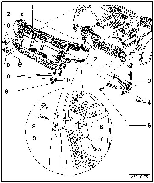
1 Lock Carrier
• Removal, refer to => [ Lock Carrier with Attachments Assembly Overview ] Lock Carrier With Attachments Assembly Overview.
• For service position, front wheel housing liner/front section removed.
• Bumper cover removed.
• Remove bolts - 2 -; - 7 -; - 9 - and - 10 -.
• Note the different lengths of bolts - 9 - and - 10 -.
• The guide rods 3411 must be installed into the threaded holes in both bolts - 10 -.
• Remove the nut on the banjo bolt at the top of the fender. => [ Securing Lock Carrier/Fender ]
• Lock carrier can now be pulled approximately 10 cm toward front and secured in this position.
2 Bolt
• M8 • 16
• 23 Nm
3 Front Brace
• Installation position, refer to => [ Front Brace Assembly Overview ] Front Brace Assembly Overview.
4 Bolt
• 25 Nm.
5 Bolt
• 25 Nm.
6 Front Brace Bracket
7 Bolt
• 23 Nm.
• Installation position, refer to => [ Front Brace Assembly Overview ] Front Brace Assembly Overview
8 Bolt
• 10 Nm.
9 Bolt
• 23 Nm
• M 8 x 30
• Not installed on vehicles without a single frame.
10 Bolt
• 23 Nm
• M8 x 40
• Note that the upper and lower bolts on the right longitudinal member have different lengths.
• Upper: M8 x 55
• Lower: M8 x 40
• For service position, only remove left bolt at top on left side and right bolt at top on right side.
• Install the (3411) into the open threaded holes=> [ Special Tool 3411 ].
• Remove bolts - 2 -; - 7 -; - 9 - and - 10 -.
• The bolt - 7 - is installed behind the front wheel housing liner/front part.
• Remove the lock carrier on the (3411) forward and then secure it.
Securing Lock Carrier/Fender
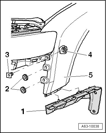
- Remove the nut - 4 - from the banjo bolt - 3 -.
- When installing, install the banjo bolt - 3 - through lock carrier and fender - 5 - and then tighten the nut - 4 - to 5 Nm.
Lock Carrier/Engine Mount Mounting
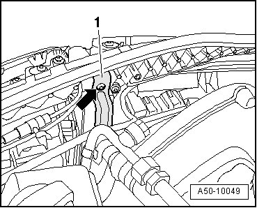
- Remove the additional threaded connector - arrow - on the support - 1 - from the engine mount.
Special Tool 3411
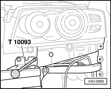
- Screw special tool 3411 into threaded holes as shown.
- For service position, lock carrier can then be pulled toward approximately 10 cm on special tool and secured in this position.
Installing Lock Carrier
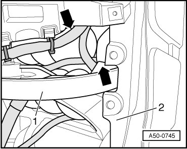
- During installation, make sure the cables or hoses - arrows - do not get caught between the lock carrier and the brace - 1 - or the fender - 2 -.