Compressor, 8 Cylinder FSI
A/C Compressor
Compressor, 8 Cylinder FSI
• Compressor is driven via a toothed gear and an driveshaft - B -.
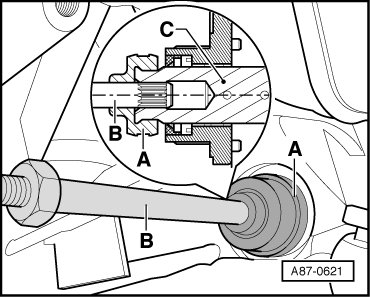
• Compressor Bracket.
• To remove the compressor on vehicles with an 8 cylinder. FSI engine, refrigerant circuit must be drained and then both refrigerant lines must be removed from compressor. Refer to => [ Refrigerant Lines, Disconnecting and Connecting from Compressor ] Removal and Replacement.
Special tools, testers and auxiliary items required
• Engine Support Bridge (10 - 222 A)
• Adapter (10 - 222 A /21)
• Used Oil Collection and Extraction Device (V.A.G 1782)
• Engine Support Supplement Set (T40093)
Removing
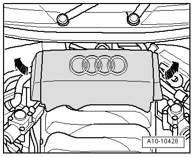
- Discharge refrigerant circuit => Refrigerant R134a - Servicing.
- Extract power-steering hydraulic oil from reservoir using Used Oil Collecting and Extracting Device (V.A.G 1782).
- Remove rear engine cover - arrows -.
- Drain coolant.
- Remove front coolant pipe.
- Remove coolant pump.
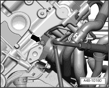
- Remove hydraulic fluid line bolt - arrow -.
- Remove oil dipstick - 10 - from guide tube.
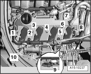
- Remove bolts - 2 - and - 5 -.
- Disconnect electrical connectors - 1, 3, 4, 6, 8 - and free up wiring harness.
- Remove Hall sensor - 9 -.
- Remove crankcase ventilation hose - 7 - by pressing release buttons.
- Lay wiring harness on engine.
- Remove bolt - 1 - and remove oil dipstick guide tube upward.
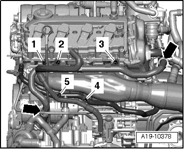
- Remove bolts - 2 - and - 3 - and pull left coolant pipe up slightly.
• Ignore - items 4, 5 and arrows -.
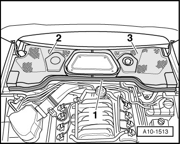
- Remove rubber seal - 1 - and remove plenum chamber covers - 2 - and - 3 -.
- Remove tower brace rear bolts - 3 -.
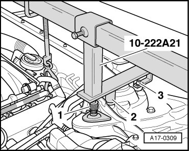
- Secure Adapter (10 - 222 A /21) without cross beam to suspension strut towers.
• The supports are marked for the left and right vehicle sides.
• Center support point - 2 - of supports is attached to front bolts for suspension strut dome.
• Adapters (10 - 222 A /21) are tightened using rear mounting bolts - 3 - for suspension strut dome.
• Knurled-head screw - 1 - must be turned downward far enough so that supporting plate makes contact on suspension strut dome.
- Install cross braces with 2 adapters (T40093/6) on adapters (10 - 222 A /21).
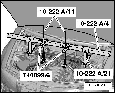
- Secure spindles (10 - 222 A /11) on engine lifting eyes.
- Slightly pre-tension engine using spindles on engine support bridge.
- Remove left and right stabilizer mount bolts - 1 - and - 2 -.
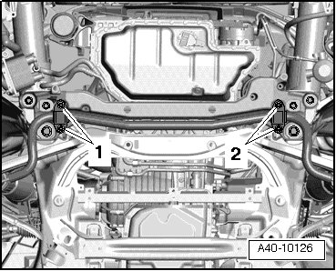
- Remove the bolts - 3 - and - 4 -.
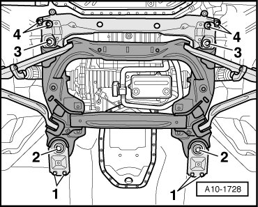
• Ignore - items 1 and 2 -.
- Remove left and right engine mount bolts - arrows - evenly.
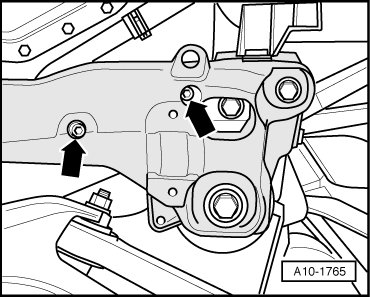
- Remove engine carrier.
• In order to collect escaping hydraulic fluid, lay a cloth under the separating point.
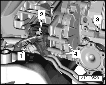
- Remove banjo fitting - 2 -.
• Ignore - items 1, 3, 4 -.
- Disconnect electrical connection on engine bracket - 1 -.
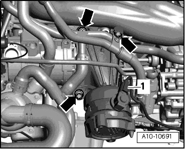
- Remove bolts - arrows - and remove engine support with engine bracket.
CAUTION!
Risk of damaging refrigerant lines and hoses.
• Do not stretch, kink or bend refrigerant lines and hoses.
- Remove bolts - 1 and 2 -.
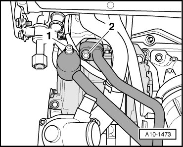
- Disconnect refrigerant lines from A/C compressor. Refer to => [ Refrigerant Lines, Disconnecting and Connecting from Compressor ] Removal and Replacement.
• To prevent dirt and moisture from entering, seal open lines and connections with clean plugs or protective caps.
- Counterhold compressor driveshaft - A - using an open-end wrench and turn compressor drive unit - B - in - direction of arrow C -.
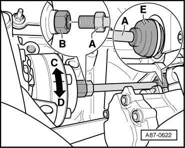
• Compressor driveshaft - A - must not be turned.
• Compressor driveshaft - A - can be slid into drive wheel through boot - E - after loosening threaded connection.
- Remove electrical connection - 1 - for A/C Compressor Regulator Valve (N280) out of bracket and disconnect it.
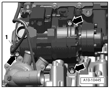
- Remove bolt - arrows -.
- Remove A/C compressor.
Installing
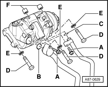
Installation is done is reverse order, observe the following:
- Check whether alignment sleeves - F - are installed in compressor.
- Tighten bolts - arrows -.
• Tightening specification: 25 Nm.
- Connect electrical connector - 1 - on A/C Compressor Regulator Valve (N280).
• Check refrigerant lines and their bracket for sufficient distances to other components.
- Attach refrigerant lines. Refer to => [ Refrigerant Lines, Disconnecting and Connecting from Compressor ] Removal and Replacement.
- Before installing compressor driveshaft - A -, install compressor drive unit - B - on compressor by rotating 10 turns by hand in - direction of arrow C - in order to avoid damage to compressor when switching on for the first time.
• Rotating forces refrigerant oil out of the compression chamber if it has accumulated there in the removed compressor or after adding fresh refrigerant oil after flushing the refrigerant circuit.
- Counterhold compressor driveshaft - A - using an open-end wrench and turn compressor drive unit - B - in - direction of arrow D -.
• Tightening specification: 60 Nm.
• Compressor driveshaft - A - must not be turned when tightening.
• After installing, check installation position of grommet - E - on drive wheel.
• A clamp on the power steering pump prevents the socket - E - from slipping off. The clamp was used in production from MY 2006. Install it if necessary. .
- Install engine support with left engine mount.
- Install subframe and engine carrier.
- Install stabilizer.
- Install coolant pump.
- Install front and left coolant pipe.
- Fill coolant and bleed coolant circuit.
- Evacuate and fill refrigerant circuit => A/C system - with refrigerant R134a.
- Operate the A/C system after filling the refrigerant circuit. Refer to => [ Operating A/C System after Filling Refrigerant Circuit ] Operating A/C System after Filling Refrigerant Circuit
• Note the information regarding operating the A/C system after filling.