Fuel Level Sensor 4, Right Tubular Sensor
Fuel Level Sensor 4, Right Tubular Sensor
Special tools, testers and auxiliary items required
• Wrench (T10202)
Removing
Observe safety precautions. Refer to => [ Safety Precautions ] Safety Precautions.
Observe rules for cleanliness, Refer to => [ Clean Working Conditions ] Clean Working Conditions.
CAUTION!
• To remove the tubular sensor, the right chamber of the fuel tank may only be filled to a maximum of 1/3. Procedure to empty the fuel tank. Refer to => [ Fuel Tank, Draining ] Procedures.
CAUTION!
Observe measures when connecting battery.
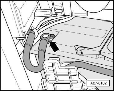
- With ignition switched off, disconnect Battery Ground (GND) cable - arrow -.
- Open fuel filler flap briefly and then close again.
- Remove the luggage compartment floor mat.
• To remove and install the tubular sensor, remove vehicle tool kit and spare wheel from luggage compartment. It is then possible to sit or kneel in spare wheel well.
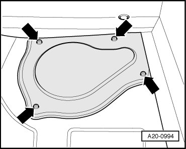
- Unbolt cover for right locking flange - arrows -.
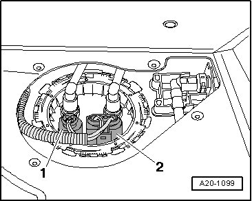
- Disconnect electrical connectors - 1 - and - 2 - at right locking flange.
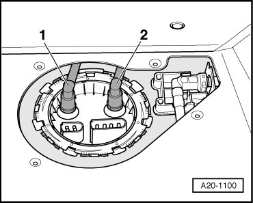
- Mark the fuel return line - 1 - and fuel supply line - 2 -.
CAUTION!
Fuel system is under pressure! Before opening system, place clean rags around the connection. Then release pressure by carefully loosening the connection.
- Pull both lines from locking flange, by pressing the release buttons.
- Remove locking ring with Wrench (T10202).
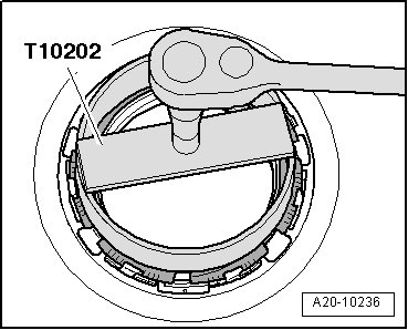
- Pull off locking flange and remove the seal.
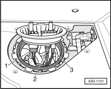
- Separate the electrical connectors - 1 to 3 - on the underside of the right locking flange.
• To separate the line couplings that are mentioned later in the description, pull the fuel lines out of the fuel tank opening.
• To improve clarity, the following illustration shows several components not installed.
Vehicles with MPI engine:
- Through the right fuel tank opening, separate the fuel lines - 1 - and - 2 - for the left fuel delivery unit by pressing the release buttons.
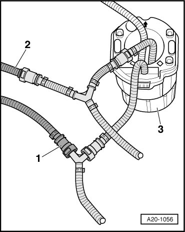
3 Right fuel delivery unit with Fuel Pump (FP) (G23)
Vehicles with FSI engine:
- Through the right fuel tank opening, separate the fuel supply lines - 1 - and - 2 - for the fuel delivery units by pressing the release buttons.
All Vehicles
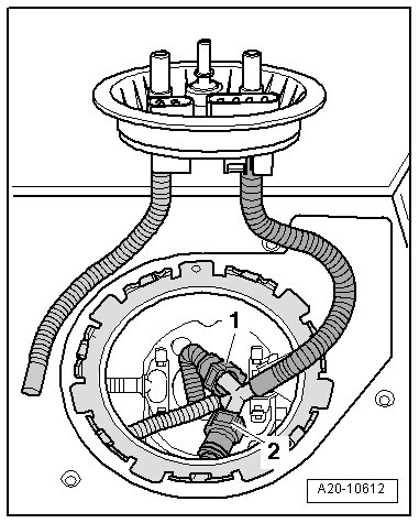
- Through the right fuel tank opening, press the release buttons - arrows - and remove the fuel delivery line - 2 - and the Fuel Level Sensor 4 (G393) - 1 -.
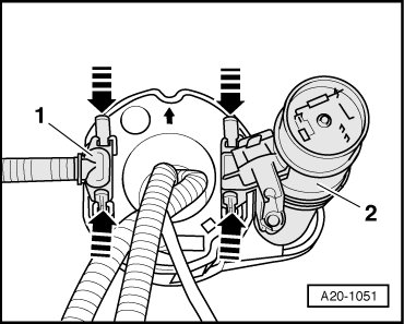
- Swing Fuel Level Sensor 4 (G393) aside to right.
- Press down both retaining clasps - arrows - on the fuel delivery unit support.
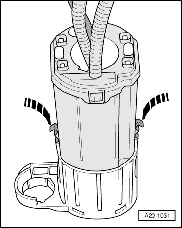
- Pull fuel rail upward slightly and remove Fuel Level Sensor 4 (G393) at the same time.
• Note that there is still fuel in Fuel Level Sensor 4 (G393).
Installing
• Tightening specifications => [ Right Fuel Delivery Unit with Fuel Pump and Fuel Gauge Assembly Overview ] .
- Before installing the fuel delivery unit, pull the retaining clasps on the support upward until it engages - arrows -.
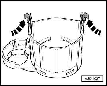
- Lift the fuel delivery unit slightly and install the Fuel Level Sensor 4 (G393).
- Carefully press the fuel delivery unit into the support until it engages audibly.
- Insert the fuel delivery line - 1 - and the Fuel Level Sensor 4 (G393) - 2 - until it engages audibly.
Vehicles with MPI engine:
- Through the right fuel tank opening, press the fuel lines - 1 - and - 2 - onto the left fuel delivery unit until they engage audibly.
3 Right fuel delivery unit with Fuel Pump (FP) (G23)
Vehicles with FSI engine:
- Reach through the right opening in the fuel tank and attach the fuel lines - 1 - and - 2 - to the fuel delivery units until they audibly engage.
All Vehicles
- Connect the electrical connectors - 1 to 3 - on the underside of the right locking flange.
- Install the new locking flange seal dry.
- Insert locking flange in fuel tank, note installation position:
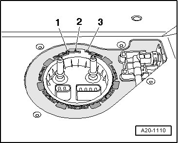
• The tab - 2 - on locking flange must lie between tabs - 1 - and - 3 - on fuel tank.
- Tighten locking ring.
- Install fuel supply line - 2 - and fuel return line - 1 - according to marking until they engage audibly.
- Connect electrical harness connectors - 1 - and - 2 - to right locking flange.
- Fasten the cover for right locking flange - arrows -.
- Connect battery. Observe safety precautions after connecting battery.