Component Locations Overview
Component Location Overview
Right Side of the Engine Compartment
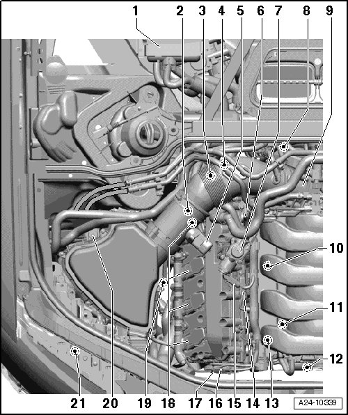
1 - Engine Control Module (ECM) (J623)
• Component location, refer to => [ ECM ].
• Removing and installing => [ Engine Control Module ] Service and Repair.
2 - Camshaft Adjustment Valve 1 (Exhaust) (N318)
3 - Secondary Air Injection (AIR) Combination Valve
• Cylinder bank 1 (right).
• Checking, removing and installing.
4 - Engine Coolant Temperature (ECT) Sensor (G62)
• Component location, refer to => [ ECT Sensor ].
5 - Mass Air Flow (MAF) Sensor (G70)/Intake Air Temperature (IAT) Sensor (G42)
• Removing and installing, refer to => [ Mass Air Flow Sensor ] Service and Repair.
6 - Camshaft Adjustment Valve 1 (N205)
• Component location, refer to => [ View From Inside the Right Cylinder Head ].
7 - High Pressure Pump
• With the fuel metering valve.
• Component location, refer to => [ High Pressure Fuel Pumps ].
• Removing and installing, refer to => [ High Pressure Pump ] High Pressure Pump.
8 - Electrical Harness Connectors
• For the Heated Oxygen Sensor (HO2S) (in front of catalytic converter) with Oxygen Sensor (O2S) heater.
• For the O2S behind Three Way Catalytic Converter (TWC) with O2S heater 1 behind TWC.
• Component location => [ Oxygen Sensor Connectors ].
9 - Throttle Valve Control Module (J338)
• After replacing the throttle valve control module, select "adapt throttle valve control module" in "Guided Functions".
10 - Knock Sensor (KS) 2 (G66), 20 Nm
• Component location, refer to => [ View From Inside the Right Cylinder Head ].
• Electrical harness connector, refer to => [ Front of Engine ].
11 - Fuel Pressure Sensor (G247), 25 Nm
• Component location, refer to => [ View From Inside the Right Cylinder Head ].
• Lubricate the threads with clean oil.
12 - Components on the Front of the Engine
• Component location, refer to => [ Front of Engine ].
• Beginning with Model Year (MY) 2009, the variable intake manifold runner motor has become the intake manifold tuning valve.
• Intake flap motor.
• Intake manifold runner position sensor
• Variable intake manifold runner motor
• Intake manifold runner position sensor 2
• Electrical connector for KS 1
• Electrical connector for KS 2
• Electrical connector for KS 3
• Electrical connector for KS 4
13 - Knock Sensor (KS) 1 (G61), 20 Nm
• Component location, refer to => [ View From Inside the Right Cylinder Head ].
• Electrical harness connector, refer to => [ Front of Engine ].
• 20 Nm
14 - Camshaft Position (CMP) sensor (G40)
• Component location, refer to => [ View From Inside the Right Cylinder Head ].
15 - Fuel Metering Valve (N290)
• Component location, refer to => [ High Pressure Fuel Pumps ].
16 - Electrical Connector for Knock Sensor (KS) 1 (G61)
• Component location, refer to => [ Front of Engine ].
17 - Electrical Connector for Knock Sensor (KS) 2 (G66)
• Component location, refer to => [ Front of Engine ].
18 - Ignition Coils, Cylinder Bank 1
• Ignition coil 1 with power output stage (N70)
• Ignition coil 2 with power output stage (N127)
• Ignition coil 3 with power output stage (N291)
• Ignition coil 4 with power output stage (N292)
• Removing and installing, refer to => [ Ignition Coils ] Service and Repair.
19 - Camshaft Position (CMP) Sensor 3 (G300)
• Attached to the outside of the cylinder head.
• Component location, refer to => [ Right Cylinder Bank 1 ].
20 - Intake Air Switch Over Valve (N335)
• Installed location, see the air filter assembly overview. Refer to => [ Air Filter Assembly Overview ] Air Filter Assembly Overview.
21 - Secondary Air Injection (AIR) Pump Motor (V101)
• Right front, below the headlamp.
• Removing and installing,
Left Side of the Engine Compartment
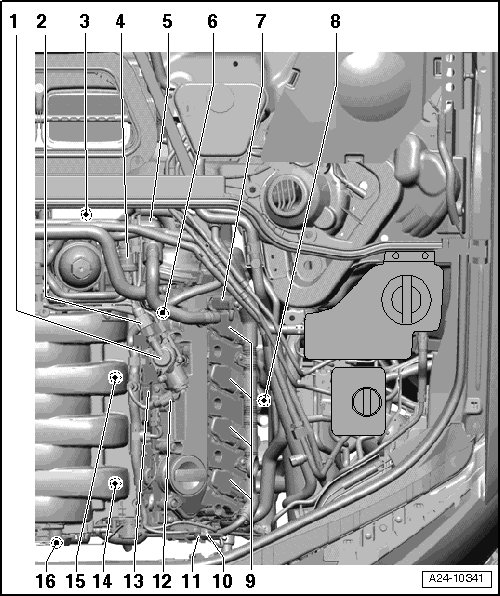
1 - High Pressure Pump
• With the fuel metering valve 2.
• Component location, refer to => [ High Pressure Fuel Pumps ].
• Removing and installing, refer to => [ High Pressure Pump ] High Pressure Pump.
2 - Low Fuel Pressure Sensor (G410)
• Component location, refer to => [ High Pressure Fuel Pumps ].
• The installed location changed in MY 2009, refer to => [ View From Inside the Left Cylinder Head (Running Change in MY 2009) ].
3 - Electrical Harness Connectors
• For the HO2S 2 (in front of catalytic converter) with O2S 2 heater.
• For the O2S 2 behind TWC with O2S heater 2 behind TWC.
• Component location, refer to => [ Oxygen Sensor Connectors ].
4 - Evaporative Emission (EVAP) Canister Purge Regulator Valve 1 (N80)
• Evaporative Emission (EVAP) canister purge solenoid valve 2 only on US vehicles.
5 - Secondary Air Injection (AIR) Combination Valve
• Cylinder bank 2 (left).
6 - Camshaft Adjustment Valve 2 (N208)
• Component location, refer to => [ View From Inside the Left Cylinder Head ].
7 - Camshaft Adjustment Valve 2 (Exhaust) (N319)
• Component location, refer to => [ Left Cylinder Bank 2 ].
8 - Camshaft Position (CMP) Sensor 4 (G301)
• Component location, refer to => [ Left Cylinder Bank 2 ].
9 - Ignition Coils, Cylinder Bank 2
• Ignition coil 5 with power output stage (N323).
• Ignition coil 6 with power output stage (N324).
• Ignition coil 7 with power output stage (N325).
• Ignition coil 8 with power output stage (N326).
• Component location, refer to => [ Left Cylinder Bank 2 ].
• Removing and installing, refer to => [ Ignition Coils ] Service and Repair.
10 - Electrical Connector for Knock Sensor (KS) 3 (G198)
• Component location, refer to => [ Front of Engine ].
11 - Electrical Connector for Knock Sensor (KS) 4 (G199)
• Component location, refer to => [ Front of Engine ].
12 - Fuel Metering Valve 2 (N402)
• Common component with the high pressure pump.
• Component location, refer to => [ High Pressure Fuel Pumps ].
13 - Camshaft Position (CMP) Sensor 2 (G163)
• Component location, refer to => [ View From Inside the Left Cylinder Head ].
14 - Knock Sensor (KS) 3 (G198), 20 Nm
• Component location, refer to => [ View From Inside the Left Cylinder Head ].
15 - Knock Sensor (KS) 4 (G199), 20 Nm
• Component location, refer to => [ View From Inside the Left Cylinder Head ].
16 - Components on the Front of the Engine
• Component location, refer to => [ Front of Engine ].
• Intake flap motor or Intake Manifold Runner Control (IMRC) valve.
• Intake manifold runner position sensor.
• Variable intake manifold runner motor or IMRC valve.
• Intake manifold runner position sensor 2.
• Electrical connector for KS 1.
• Electrical connector for KS 2.
• Electrical connector for KS 3.
• Electrical connector for KS 4.
A - Engine Speed (RPM) Sensor (G28)
• Component location, refer to => [ Engine Speed (RPM) Sensor ].
B - Throttle Position (TP) Sensor (G79)/Accelerator Pedal Position Sensor 2 (G185)
• In the footwell on the accelerator pedal (both sensors are integrated into one housing).
• Component location, refer to => [ TP Sensor/Accelerator Pedal Position Sensor 2 ].
C - Kick Down Switch (F8)
• In the footwell, at the accelerator pedal.
• Component location, refer to => [ Kick Down Switch ].
D - Brake Light Switch (F)/Brake Pedal Switch (F47)
• In the footwell at the brake pedal.
• Component location, refer to => [ Brake Light Switch/Brake Pedal Switch ].
E - Clutch Pedal Switch (F36)
• In the footwell on the clutch pedal.
F - Fuel Pump (FP) Control Module (J538)
• Component location, refer to => [ Fuel Pump Control Module ].
G - Oil Pressure Switch (F1)
• Component location, Refer to => [ Oil Pressure Switch ].
H - Heated Oxygen Sensor (HO2S) (G39) before Catalytic Converter with Oxygen Sensor (O2S) Heater (Z19), 55 Nm
• Location of electrical connector, refer to => [ Oxygen Sensor Connectors ].
• Component location of oxygen sensors, refer to => [ Oxygen Sensors, Cylinder Bank 1 (Right) ].
• Removing and installing, refer to => [ Oxygen Sensors, Cylinder Bank 1 ] Oxygen Sensors, Cylinder Bank 1.
I - Heated Oxygen Sensor (HO2S) 2 (G108) before Catalytic Converter with Oxygen Sensor (O2S) 2 Heater (Z28), 55 Nm
• Location of electrical connector, refer to => [ Oxygen Sensor Connectors ].
• Component location of oxygen sensors, refer to => [ Oxygen Sensors, Cylinder Bank 2 (Left) ].
• Removing and installing, refer to => [ Oxygen Sensors, Cylinder Bank 2 ] Oxygen Sensors, Cylinder Bank 2.
J - Oxygen Sensor (O2S) behind Three Way Catalytic Converter (TWC) (G130) with Oxygen Sensor (O2S) 1 behind Three Way Catalytic Converter (TWC) Heater (Z29), 55 Nm
• Location of electrical connector, refer to => [ Oxygen Sensor Connectors ].
• Component location of oxygen sensors, refer to => [ Oxygen Sensors, Cylinder Bank 1 (Right) ].
• Removing and installing, refer to => [ Oxygen Sensors, Cylinder Bank 1 ] Oxygen Sensors, Cylinder Bank 1.
K - Oxygen Sensor (O2S) 2 behind Three Way Catalytic Converter (TWC) (G131) with Oxygen Sensor (O2S) 2 behind Three Way Catalytic Converter (TWC) Heater (Z30), 55 Nm
• Location of electrical connector, refer to => [ Oxygen Sensor Connectors ].
• Component location of oxygen sensors, refer to => [ Oxygen Sensors, Cylinder Bank 2 (Left) ].
• Removing and installing, refer to => [ Oxygen Sensors, Cylinder Bank 2 ] Oxygen Sensors, Cylinder Bank 2.
ECM
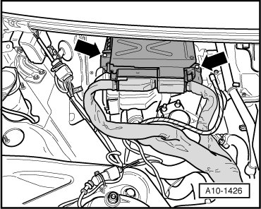
Removing and installing, refer to => [ Engine Control Module ] Service and Repair.
Relay and Fuse Holder in Right Footwell
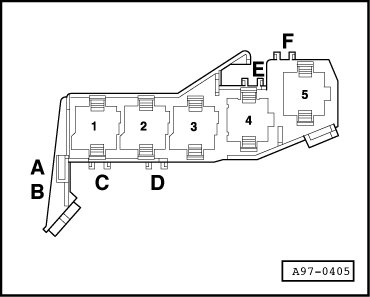
2 Starter relay
3 Starter relay 2
4 Fuel pump relay
Relay and Fuse Holder behind Left Instrument Panel
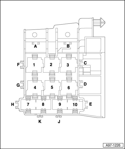
3 Power supply relay (terminal 15)
4-Pin Relay Carrier in E-box Plenum Chamber
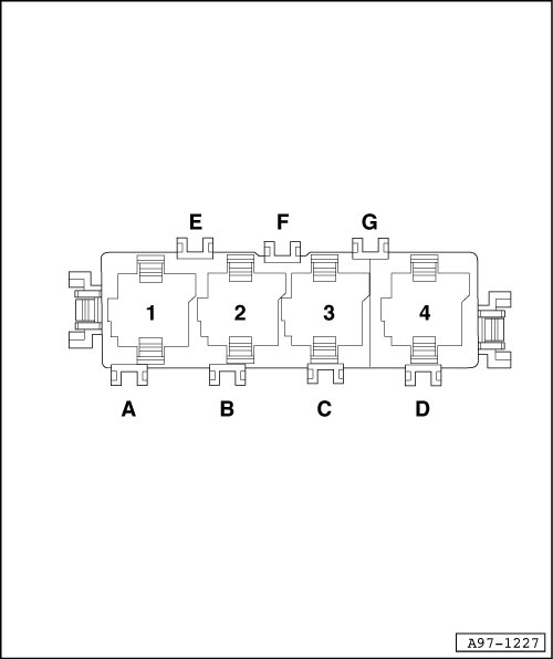
1 AIR pump relay
2 Motronic ECM power supply relay
TP Sensor/Accelerator Pedal Position Sensor 2
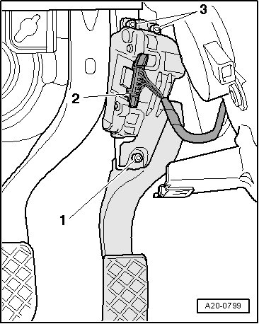
• The TP sensor and accelerator pedal position sensor 2 are integrated in the accelerator pedal module and cannot be replaced individually.
Kick Down Switch
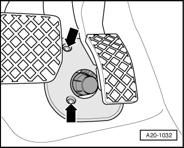
Brake Light Switch/Brake Pedal Switch
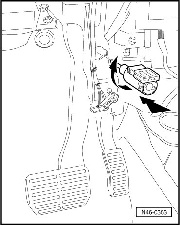
• Removing and installing
• To ensure that they are absolutely securely seated, the switches may only be installed once.
Fuel Pump Control Module
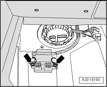
Installed location: Under the floor covering on the left side of the luggage compartment.
Bolts - arrows -.
Oxygen Sensor Connectors
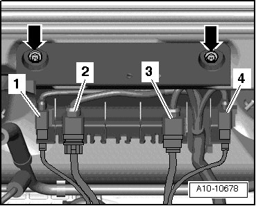
1. To the HO2S
2. To the O2S behind TWC
3. To the HO2S 2
4. To the O2S 2 behind TWC
Oxygen Sensors, Cylinder Bank 1 (Right)

1. O2S behind TWC
2. HO2S
Tightening specification: 55 Nm
Oxygen Sensors, Cylinder Bank 2 (Left)
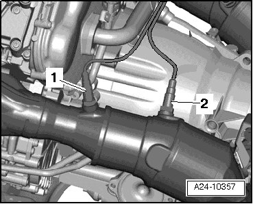
1. HO2S 2
2. O2S 2 behind TWC
Tightening specification: 55 Nm
Engine Speed (RPM) Sensor
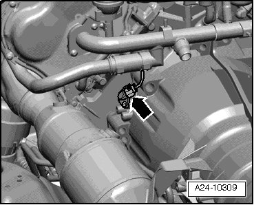
Engine Speed (RPM) sensor - arrow -.
ECT Sensor
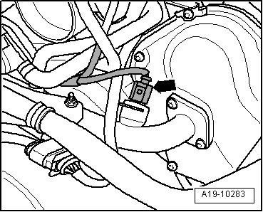
• ECT sensor - arrow -.
• Right side, on the rear coolant pipe - arrow -.
• Removing and installing.
Right Cylinder Bank 1
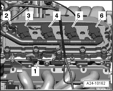
1. CMP sensor 3
2. Camshaft adjustment valve 1 (exhaust)
3. Ignition coil 4 with power output stage
4. Ignition coil 3 with power output stage
5. Ignition coil 2 with power output stage
6. Ignition coil 1 with power output stage
Left Cylinder Bank 2
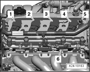
1. Ignition coil 5 with power output stage
2. Ignition coil 6 with power output stage
3. Ignition coil 7 with power output stage
4. Ignition coil 8 with power output stage
5. Camshaft adjustment valve 2 (exhaust)
6. CMP sensor 4
View From Inside the Right Cylinder Head
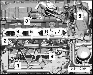
1. Fuel pressure sensor
2. KS 1
3. CMP sensor
4. Cylinder 1 fuel injector
5. Cylinder 2 fuel injector
6. Cylinder 3 fuel injector
7. Cylinder 4 fuel injector
8. Camshaft adjustment valve 1
9. KS 2
View From Inside the Right Cylinder Head (Running Change in MY 2009)
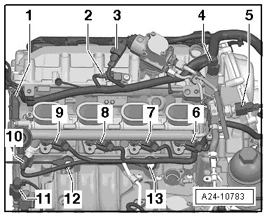
1. Intake manifold runner position sensor
2. CMP sensor
3. Fuel metering valve
4. Camshaft adjustment valve 1
5. Low fuel pressure sensor
6. Cylinder 1 fuel injector
7. Cylinder 2 fuel injector
8. Cylinder 3 fuel injector
9. Cylinder 4 fuel injector
10. Fuel pressure sensor
11. IMRC valve
12. KS 1
13. KS 2
View From Inside the Left Cylinder Head
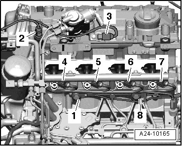
1. KS 4
2. Camshaft adjustment valve 2
3. CMP sensor 2
4. Cylinder 8 fuel injector
5. Cylinder 7 fuel injector
6. Cylinder 6 fuel injector
7. Cylinder 5 fuel injector
8. KS 3
View From Inside the Left Cylinder Head (Running Change in MY 2009)
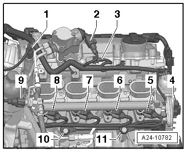
1. Camshaft adjustment valve 2
2. Fuel metering valve 2 (attached into the high pressure pump)
3. CMP sensor 2
4. Intake manifold runner position sensor 2
5. Cylinder 5 fuel injector
6. Cylinder 6 fuel injector
7. Cylinder 7 fuel injector
8. Cylinder 8 fuel injector
9. Low fuel pressure sensor
10. KS 4
11. KS 3
Front of Engine
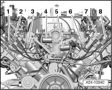
1 KS 2 (brown connector)
2 KS 1 (black connector)
3 Intake manifold runner position sensor
4 Variable intake manifold runner motor (black connector)
5 Intake flap motor (brown connector)
6 Intake manifold runner position sensor 2
7 KS 4 (black connector)
8 KS 3 (brown connector)
Running change in MY 2009 - items 4 and 5 - are being replaced by vacuum controlled valves (see the following illustration).
• The intake flap motor has become the intake manifold runner control valve.
• The variable intake manifold runner motor has become the intake manifold tuning valve.
Front of Engine (Running Change in MY 2009)
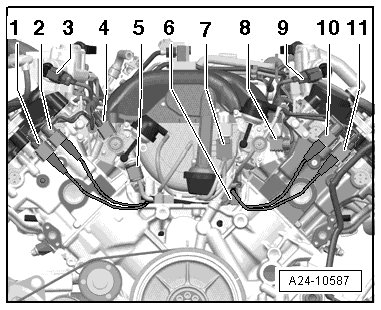
1 KS 2 (brown connector)
2 KS 1 (black connector)
3 Low fuel pressure sensor
4 Intake manifold runner position sensor
5 Fuel pressure sensor
6 Intake manifold runner control valve (CVTS tumble flaps)
7 IMT valve
8 Intake manifold runner position sensor 2
9 Fuel metering valve
10 KS 4 (black connector)
11 KS 3 (brown connector)
Oil Pressure Switch
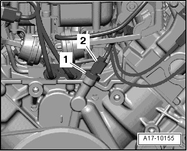
Oil pressure switch - 1 - and electrical connector - 2 -.
High Pressure Fuel Pumps
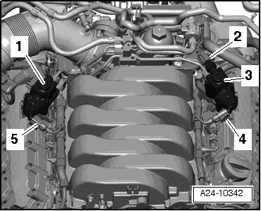
1 Right high pressure pump (cylinder bank 1)
2 Low fuel pressure sensor
3 Left high pressure pump (cylinder bank 2)
4 Fuel metering valve 2
5 Fuel metering valve
Map Controlled Engine Cooling Thermostat
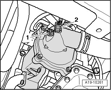
• At the left front of the engine.
2 Map controlled engine cooling thermostat
• Ignore - item 1 -.