Secondary Air Injection System Version 2 Assembly Overview
Secondary Air Injection System Version 2 Assembly Overview
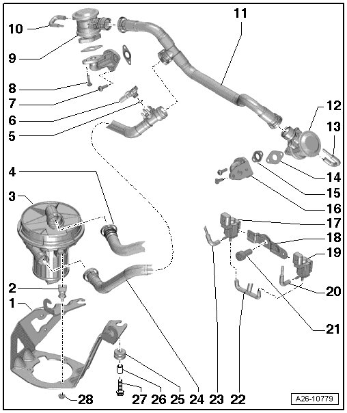
1 Bracket
• For Secondary Air Injection (AIR) pump motor (V101)
2 Bonded Rubber Bushing
3 Secondary Air Injection (AIR) Pump Motor (V101)
• Component location: At front right in engine compartment below the longitudinal member
• Removal and installation, refer to => [ Secondary Air Injection Pump ] Secondary Air Injection Pump
• Check in "Guided Fault-Finding" operating mode, refer to -> vehicle diagnostic tester.
4 Hose
• From air filter housing
5 O-ring
• Replace
6 Secondary Air Injection Sensor 1 (G609)
• Removal and installation, refer to => [ Fuel Level Sensor 1 ] Fuel Level Sensor 1
7 Bolt
• 9 Nm
8 Bolt
• 9 Nm
9 Right secondary air injection (AIR) combination valve
• Component location: On the front of the right cylinder head
• Checking, refer to => [ Secondary Air Injection Combination Valves, Version 2, Checking for Function and Leaks ] Secondary Air Injection Combination Valves, Version 2, Checking For Function and Leaks
• Removal and installation, refer to => [ Secondary Air Injection Right Combination Valve ] Secondary Air Injection Right Combination Valve
10 Vacuum Hose
• To the right secondary air injection combination valve
11 Hose
• To Secondary Air Injection (AIR) combi-valves
12 Left secondary air injection (AIR) combination valve
• Component location: On the front of the left cylinder head
• Checking, refer to => [ Secondary Air Injection Combination Valves, Version 2, Checking for Function and Leaks ] Secondary Air Injection Combination Valves, Version 2, Checking For Function and Leaks
• Removal and installation, refer to => [ Secondary Air Injection Left Combination Valve ] Secondary Air Injection Left Combination Valve
13 Vacuum Hose
• To the left secondary air injection combination valve
14 Gasket
• Replace
15 Gasket
• Replace
16 Flange
• To cylinder head
17 Secondary air injection (AIR) solenoid valve (N112)
18 Bracket
• For the secondary air injection (AIR) solenoid valve
19 Secondary Air Injection (AIR) Solenoid Valve 2 (N320)
20 Vacuum Hose
• From the secondary air injection solenoid valve 2 (N320)
21 Bolt
• 9 Nm
22 Vacuum Hose
• With a T-piece
• Vacuum supply from intake manifold
23 Vacuum Hose
• From the secondary air injection solenoid valve (N112)
24 Hose
• From Secondary Air Injection (AIR) Pump Motor (V101) to secondary air injection combi-valves
25 Grommet
26 Bushing
27 Bolt
• 9 Nm
28 Nut
• 9 Nm
Component Location for Secondary Air Injection (AIR) Pump Relay (J299)
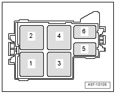
• In E-box, plenum chamber.
4 Secondary Air Injection (AIR) pump relay (J299)
• The Secondary Air Injection (AIR) pump fuse (S130) is located on a separate bracket.
Secondary Air Injection (AIR) Solenoid Valve Installation Location
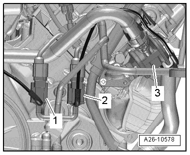
• On the front of the left cylinder head.
1. Secondary air injection (AIR) solenoid valve (N112)
2. Secondary Air Injection (AIR) Solenoid Valve 2 (N320)