Steering Column Electronic Systems Control Module
Steering Column Electronic Systems Control Module
Special tools, testers and auxiliary items required
• 2.5 mm diameter drill; length at least 75 mm (3. in.)
Removing
Risk of damaging coil connector.
• The coil connector and slip ring must not be twisted when it removed (secure it with adhesive tape).
Risk of destroying electronic components with static discharge.
• To discharge static, touch vehicle ground with hand (while not wearing gloves).
- If the control module was replaced, select the Replace function for the respective control module in Guided Fault Finding or Guided Functions.
- Select the function or path:

- Follow the instructions on the Vehicle Diagnosis Tester display.
- Remove the steering wheel and adjustment mechanism completely and lay it down.
- Remove the airbag unit and steering wheel.
- Remove the steering column switch module trim.
- Disconnect electrical connector - 4 - on steering column electronic systems control module (J527) - item 1 - by removing fuse - 3 - - arrow - and pressing release down.
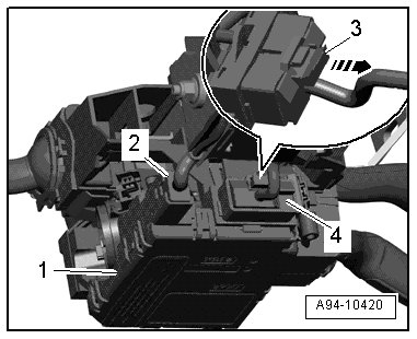
- Disconnect electrical connector - 2 -.
- Remove bolt - 1 -.
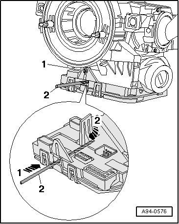
- At steering column electronic systems control module, slide a 2.5 mm drill - item 2 - approximately 45 mm (1.75 in.) into the hole - arrow 1 -, releasing the retaining detent - arrow 2 -.
- Pull steering column electronic systems control module down slightly and remove drill.
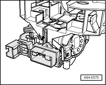
- Release retaining clip - arrow - on connector side of steering column electronic systems control module and remove control module from steering column switch module.
Installing
Install in reverse order of removal, noting the following:
- Make sure all retaining hooks and connectors are engaged securely.
- Install the steering column switch module trim.
- Install the airbag unit and steering wheel.
If steering column electronic systems control module was replaced, it must be coded.
- Select the function or path
- Follow the instructions on the Vehicle Diagnosis Tester display.
Tightening Specifications
