Fuel Level Sensor 2 (G169), Checking
Fuel Level Sensor 2 (G169), Checking
Special tools, testers and auxiliary items required
• Multimeter (V.A.G 1526D)
• Connector Test Set (V.A.G 1594C)
Procedure
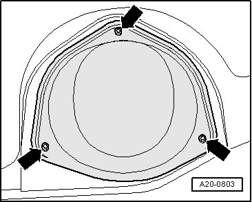
• The electric wires for fuel level sensor 2 are routed to the fuel pump locking flange inside the fuel tank.
- Remove the rear bench seat.
- Remove the locking flange cover - arrows -.
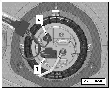
- Disconnect the connectors - 1 and 2 - - 2 - on the locking flange.
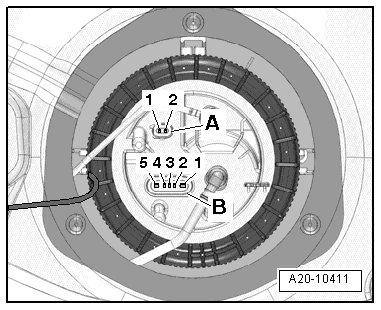
- Connect the multimeter for the resistance measurement between terminal - 2 - on the connector - A - and terminal - 2 - on the connector - B -.
Fuel level sensor 2 installed:
• Sensor at lower stop: approximately 290 ohms.
• Sensor at upper stop: approximately 45 ohms.
• If measured value is 0 ohms there is a short circuit. If measured value is there is and open circuit in the wiring.
• To check resistance values "tank full" or "tank empty", the fuel level sensor 2 (G169) must be removed. Refer to => [ Fuel Level Sensor 2 (G169) ] Fuel Level Sensor 2 (G169) and the sensor floater must be placed in the upper or lower end position.
• With fuel gauge sensor removed, the following values are obtained because of the greater deflection of the floater arm:
Fuel level sensor 2 removed:
• Sensor at lower stop: approximately 290 ohms.
• Sensor at upper stop: approximately 16 ohms.
- Connect the multimeter between terminals - 1 and 2 - on connector - A - to measure the resistance.
Fuel level sensor 2 installed or removed:
• Any sensor position: approximately 340 ohms.
Assemble in reverse order of disassembling. Note the following:
- Install the right locking flange cover. Refer to => [ Locking Flange Cover - Tightening Specifications ] Fuel Tank With Attachments Overview.
- Install the rear bench seat.