Front Suspension
Subframe
Special tools, testers and auxiliary items required
• Engine support bridge (10-222 A)
• Torque wrench (V.A.G 1331)
• Torque wrench (V.A.G 1332)
• Engine/transmission jack (V.A.G 1383 A)
• Vehicle Diagnostic, Testing and Information System (VAS 5051 B) with corresponding diagnostic cable.
• Tensioning strap (T10038)
• Wheel hub support (T10149)
• Engine Support Basic Set (T40091)
• Engine Support Supplement Set (T40092)
• Engine Support Supplement Set (T40093)
Removing
Affects Vehicles with Air Suspension
- Place the vehicle on a hoist. Refer to => [ Positioning Vehicle on Hoist and Wheels ] Positioning Vehicle on Hoist and Wheels.
- Perform system vent using (VAS 5051 A). Refer to => [ System, Venting or Filling ] System, Venting or Filling.
Affects All Vehicles
- Remove noise insulation.
- Remove wheel trim cap, remove cover cap on light-alloy wheels (removal hook in vehicle tool kit).
- Remove wheels.
Relevant for Vehicles with Auxiliary Heater
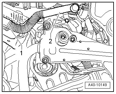
- Remove muffler - 1 - for auxiliary heater with exhaust pipe - 2 -.
Affects All Vehicles
- Remove the right and left coupling rod. Refer to => [ Coupling Rod ] Coupling Rod.
- Remove the stabilizer bar. Refer to => [ Stabilizer Bar ] Stabilizer Bar.
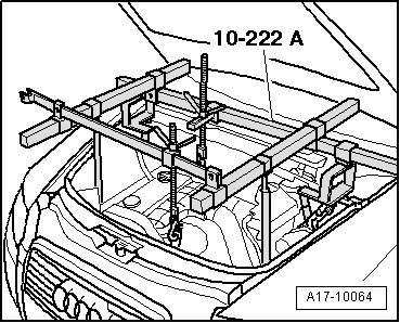
- Support the engine entirely using the (10-222 A).
- Assemble (10-222 A) using (T40091) , (T40092) and (T40093) on suspension strut domes and longitudinal members, as shown in illustration.
- Remove the left and right nuts - 1 -.

- In vehicles with level control system sensor, unscrew nut - 2 - on both sides.
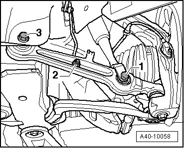
- Disconnect connector from level control system sensor on left and right sides.
- Remove the left and right hex bolt - 1 -.
- Secure both wheel bearing housings with (T10038) as illustrated.
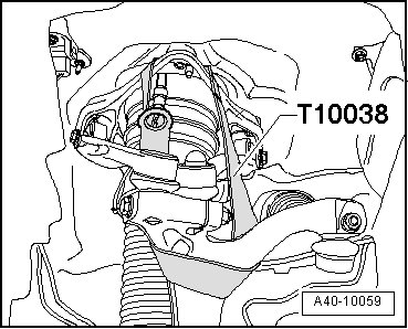
• To prevent the joints on the upper control arm from being damaged, support the wheel bearing housing.
- Disconnect threaded connection from both guide control arms - 1 - and track control arms - 2 - on subframe side. Tie up guide control arm and track control arm using wire - arrows -.
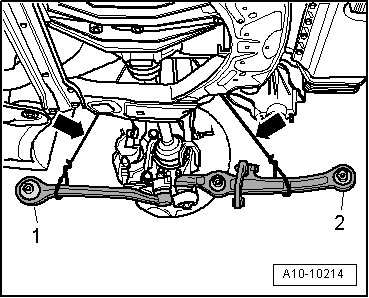
• In order not to overbend the joints of track control arm and guide control arm, they must be fastened to the body with a tie wire or something like it.
- Place (V.A.G 1383 A) with wooden block under subframe and press lightly against.
- Remove hex bolts - 5 - and - 6 -.
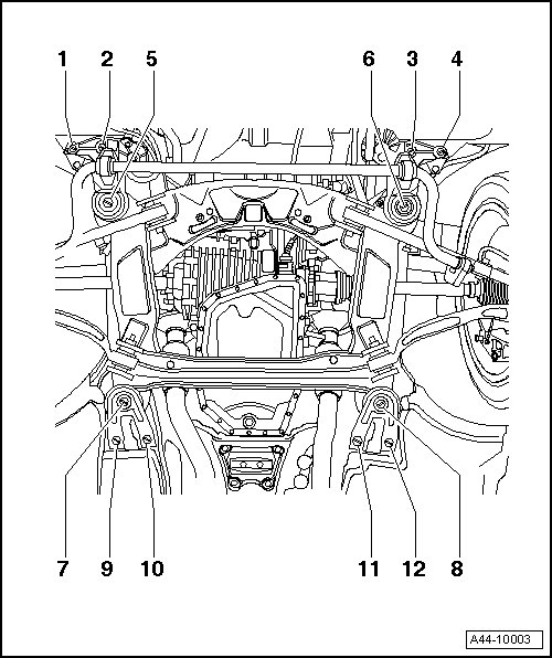
- Remove the bolts - 7 - through - 12 - and lower the rear subframe.
- Loosen the bolts - 1 - through - 4 - just enough until it is possible to move the subframe.
Installing
Install in reverse order of removal. Note the following:
When assembling the subframe and the engine mount bracket, pay attention to correct fit.
- The center of the subframe mount holes must be aligned to the bolting points on the body.
• Bonded rubber bushings can only be turned to a limited extent. Only tighten suspension screws when vehicle is in curb weight or control position.
• Wheel bearing, lifting to curb weight position on vehicles with coil springs, refer to => [ Wheel Bearing, with Coil Spring, Lifting to Curb Weight Position ] Wheel Bearing, with Coil Spring, Lifting to Curb Weight Position.
• Wheel bearing, lifting to control position on vehicles with air suspension, refer to => [ Wheel Bearing, with Air Suspension, Lifting to Curb Weight Position ] Wheel Bearing, with Air Suspension, Lifting to Curb Weight Position.
Tightening specifications, refer to => [ Subframe, Engine Mount Bracket, Stabilizer Bar, Crossmember and Coupling Rod Assembly Overview ] Subframe, Engine Mount Bracket, Stabilizer Bar, Crossmember and Coupling Rod Assembly Overview.
- Install the wheels.
- On vehicles with air suspension, position vehicle on wheels. Refer to => [ Positioning Vehicle on Hoist and Wheels ] Positioning Vehicle on Hoist and Wheels.
- Tighten wheels.
- Adapt control position anew on vehicles with air spring suspension. Refer to => [ Self-Leveling Suspension Control Position, Programming ] Self-Leveling Suspension Control Position, Programming.
- On vehicles with automatic headlamp range control system, perform a basic setting on the headlamps.
- Perform an axle alignment. Refer to => [ Wheel Alignment ] Wheel Alignment.
• The axle alignment on the front and rear axles must be performed on a VW/Audi approved alignment rack.