Leak Detection Pump, 8-Cylinder MPI, Checking
Leak Detection Pump, 8-Cylinder MPI, Checking
Special tools, testers and auxiliary items required
• Hand-held multimeter (V.A.G 1526C)
• Voltage tester (V.A.G 1527B)
• Connector test set (V.A.G 1594C)
• Adapter cable, 121-pin (V.A.G 1598/31)
• Vehicle diagnostic, testing, and information system (VAS 5051B) with Diagnostic Cable (VAS 5051/5A)
Procedure
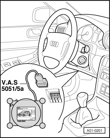
• Ignition switched on.
• (VAS 5051B) connected with (VAS 5051/5A), Vehicle Self-Diagnosis selected.
Check Activation
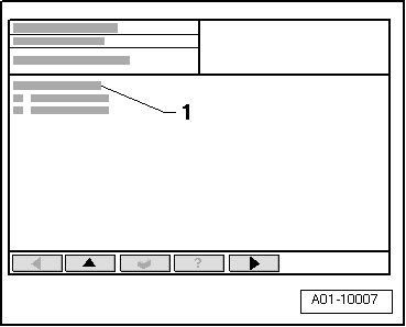
Display on (VAS 5051B):
- Tap "On Board Diagnostic" in selection - 1 - and activate by tapping the -> button.
Display on (VAS 5051B):
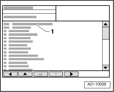
- Tap "01 - Engine Electronics" vehicle system in selection - 1 - and activate by tapping the -> button.
Display on (VAS 5051B):
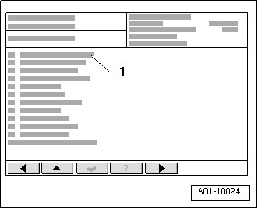
- Tap "005 - Output Diagnostic Test Mode (DTM)" function in selection - 1 - and activate by pressing the -> button.
Display on (VAS 5051B):
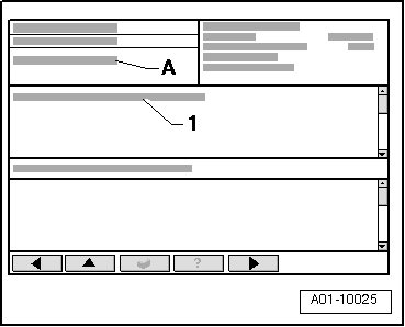
A Output diagnostic test mode waiting, Advancing by switching required
1 Evaporative Emission (EVAP) Canister Purge Regulator Valve 1 (N80)
- Press the -> button repeatedly, until Leak Detection Pump (LDP) (V144) is activated.
• The sound of the leak detection pump running can be heard at the left rear wheel housing.
- End function "005 - output Diagnostic Test Mode (DTM)" by pressing <- button.
- Select "022 - End output" function in selection.
- Switch off ignition.
If Leak Detection Pump (LDP) for fuel system is not activated (no operating noise audible):
- Remove leak detection pump (LDP) and disconnect the electrical connection. Refer to => [ Leak Detection Pump ] Service and Repair.
Checking internal resistance
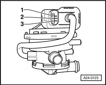
- Connect (V.A.G 1526C) for resistance measurement as follows.
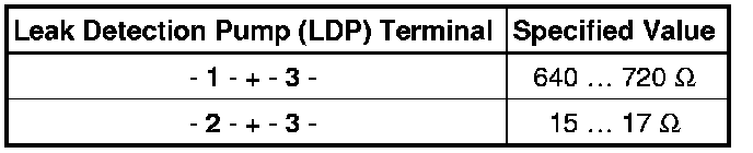
If the specifications are not obtained:
- Replace the leak detection pump (LDP). Refer to => [ Leak Detection Pump ] Service and Repair.
If the specified values are achieved:
- Check voltage supply of leak detection pump.
Checking voltage supply
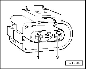
• Voltage for leak detection pump is supplied via Motronic Engine Control Module (ECM) Power Supply Relay (J271).
• Fuse for leak detection pump OK
- Connect (V.A.G 1527B) as follows:

- Briefly operate starter.
• LED must light up.
If LED does not light up:
- Check electrical harness connection from terminal - 3 - via fuse to Motronic engine control module (ECM) power supply relay for open circuit according to wiring diagram.
- Repair open circuit in wiring according to wiring diagram.
Checking output wiring
- Connect (V.A.G 1527B) as follows:

- Initiate output Diagnostic Test Mode (DTM).
Display on (VAS 5051B):
A Output diagnostic test mode waiting, Advancing by switching required.
1 Evaporative emission (EVAP) canister purge regulator valve 1.
- Press the -> button repeatedly, until leak detection pump for fuel system is activated.
• LED must blink.
If LED does not blink:
- End function "005 - output Diagnostic Test Mode (DTM)" by pressing <- button.
- Select "022 - End output" function in selection.
- Switch off ignition.
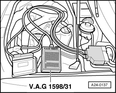
- Connect (V.A.G 1598/31) to wiring harness connectors, do not connect engine control module. Connect ground (GND) clip at test box to Ground (GND) (not visible in illustration).
CAUTION!
Risk of destroying electrical components.
• Before connecting the test leads, switch on the respective measuring range and observe the test conditions.
- Check the following wire connection for open circuit and short circuit to Ground (GND) and B+:

- Repair wiring open circuit or short circuit according to wiring diagram.
If no malfunction is found, but leak diagnosis pump is not functional during output diagnostic test mode:
- Replace the leak detection pump (LDP). Refer to => [ Leak Detection Pump ] Service and Repair.
- Observe procedures for after re-connecting engine control module (ECM).
Checking input wiring
- Switch off ignition.
- Connect (V.A.G 1598/31) to wiring harness connectors, do not connect engine control module. Connect Ground (GND) clip at test box to Ground (GND) (not visible in illustration).
CAUTION!
Risk of destroying electrical components.
• Before connecting the test leads, switch on the respective measuring range and observe the test conditions.
- Check the following wire connection for open circuit and short circuit to ground (GND) and B+:

- Repair wiring open circuit or short circuit according to wiring diagram.
- Observe procedures for after re-connecting engine control module (ECM).