Front Subframe Mount: Adjustments
Subframe Mount, Adjusting
Special tools, testers and auxiliary items required
• Engine Support Bridge (10 - 222 A)
• Shackle (10 - 222 A /12)
• Special Hook (10 - 222 A /20)
• Engine Sling (2024 A)
• Adapter (T40093/6) qty. 2
Procedure
• For the correct tightening specifications, refer to => [ Engine and Transmission Mounts Overview ] Service and Repair.
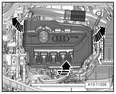
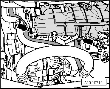
- Remove the engine cover - arrows -.
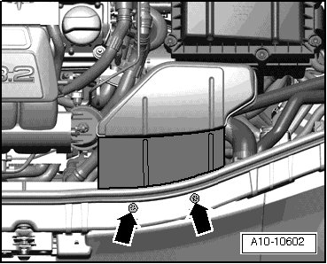
- Remove the bolts - arrows - and air guide.
- Remove the coolant hose by loosening the hose clamp - 1 -.
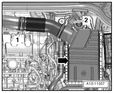
- Disconnect the connector - 2 - from the Mass Airflow (MAF) Sensor (G70).
- Detach upper section of the air filter housing - arrow - and remove air filter insert.
- Remove the bolts - arrows - and the lower section of the air filter housing.
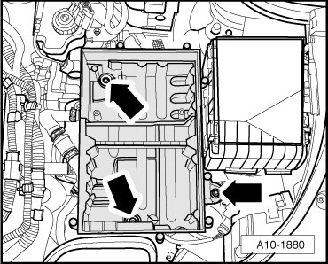
- Remove the bolts - arrows - and the air filter housing bracket.
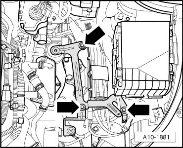
- Remove the bolt and nut - arrows - and then push the front right coolant pipe to the side with the coolant hoses still connected.
- Place the (10 - 222 A) on upper edge of web plates with the following tool parts:
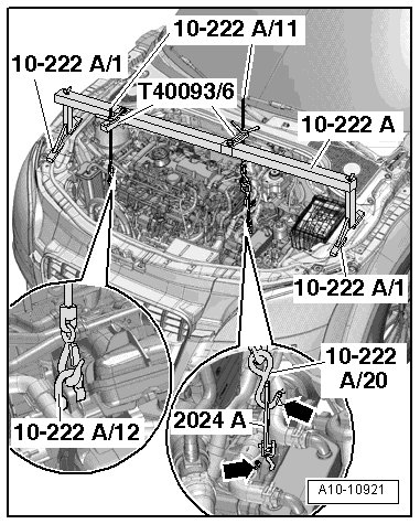
• Engine brackets (10 - 222 A /1) , quantity: 2
• Spindle (10 - 222 A /11) ; quantity: 2
• Shackle (10 - 222 A /12)
• Adapter (10 - 222 A /20)
• Engine sling (2024 A) hook
• Adapter (T40093/6) qty. 2
- Engage the spindle (10 - 222 A /11) with (10 - 222 A /12) on the left transmission lifting eye.
- Attach the (10 - 222 A /11) , (10 - 222 A /20) and (2024 A) hook to the transmission.
Risk of accident.
• Lifting hooks and alignment pins on lifting tackle must be secured with securing pins - arrows -.
- Tension engine/transmission subframe by evenly tightening the 2 spindles.
- Remove the subframe bolts - arrows - on the engine side.
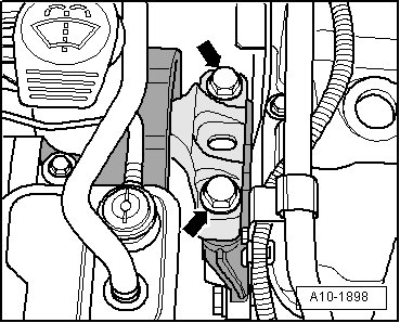
- Remove the subframe bolts - arrows - on the transmission side.
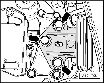
- Replace all 5 bolts in succession (if not already done when installing engine) hand tighten.
- Loosen the left and right support arm bolts approximately 2 turns.
- Slide engine/transmission assembly with a pry bar between engine mount - 1 - and engine support - 4 - until the following dimensions are set:
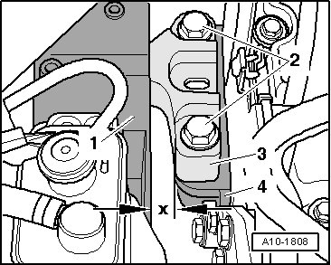
• Both bolt heads - 2 - must be parallel to edge of support arm - 3 -.
• A distance of - x - = 16 mm must be present between engine mount - 1 - and engine support - 4 -.
• Distance - x - = 16 mm can also be checked with corresponding round stock.
- Tighten subframe mount bolts on the transmission side.
- The edges on the support arm - 1 - and transmission mount - 2 - are parallel on the transmission side.

• Dimension - x - same size on both sides of bracket.
- Tighten subframe mount bolts on the engine side.
The rest of the installation is performed in reverse order of removal, noting the following:
• The hose supports, air guide pipes and hoses must be free of oil and grease before installing.
• Secure all hose connections with hose clamps appropriate for the model. Refer to the electronic parts catalog ETKA.
- Tighten the bolts for front section of the longitudinal member.
- Remove the (10 - 222 A).
- Install the front right coolant pipe. Refer to => [ Right Front Coolant Pipe ] Right Front Coolant Pipe.
- Install the air filter housing and the air filter.